Because of the holidays, TI E2E™ design support forum responses will be delayed from Dec. 25 through Jan. 2. Thank you for your patience.

This thread has been locked.

If you have a related question, please click the "Ask a related question" button in the top right corner. The newly created question will be automatically linked to this question.

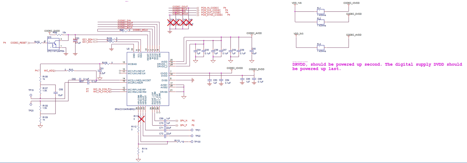
TLV320AIC3104-Q1: Help to check the differential microphone schematic design

Part Number: TLV320AIC3104-Q1

Dear team,

1. Could you please help to check if the customer's differential microphone schematic is correct?

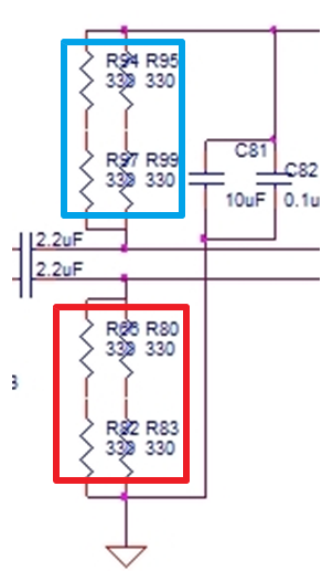
2. If the four resistors marked in the red box below are changed to 0R and connected to the ground, and the pull-up resistors marked in the blue box below use the 680R. Can this design be turned into a hardware design for a single-ended microphone?  Is the connection between the codec pin and the differential microphone compatible?

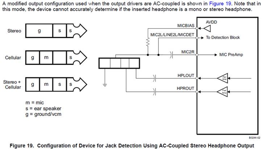
3. What I also want to know is how does the 3104 do a single-ended microphone (or differential microphone) insertion detection function? How should the hardware be designed? Is the 3104's microphone detection function only available when using the mic2 channel? Can I use the mic1 channel to realize this function? How do you design a microphone detection circuit if the microphone input uses the mic1R/L channel?

Thanks & Best Regards,

Sherry

  • Sherry,

    1. the mic bias should never have a capacitor on it. the aic3104 was not designed for this, and at startup the charging current will be high and could damage the device, they could change R105, but as this is not a recommended practice, TI does not have any guidance for values. Also the unused inputs should be tied together and AC coupled to gnd with a 0.47uf capacitor.

    2. Yes, they could change the values and use 0R for the red box and that would be SE configuration.

    3. The AIC3104 does not do SE detection, this must be manually configured on the codec. In SE mode the negative input is terminated to an internal common mode.

    we have seen customers DC couple the inputs of unused channels to do HP load detection etc... but TI doesn't have a recommended method for doing this. The thing to be concerned with here, is that you have an 8V mic bias, and its a good possibility that in differential mode that the negative terminal of the mic would approach the ABSMAX voltage for the input pin (AVDD+0.3V) so you wouldn't be able to do this directly. there would need to be some circuitry to buffer the codec from the negative input pin.

    best regards,
    -Steve Wilson
  • Hi Steve,

    1. how does the 3104 do a differential microphone insertion detection function? Could you please show it on the schematic I sent to you?
    2. You said SE detection must be manually configured on the codec. Could you please give me an example how to configure it manually?
    3. One customer demand is that the Tbox does not have an amplifier, and the codec outputs an analog signal (via the HP 4 pins) to the speaker of the car (IVI device). Could you please help to see how these two pins (HPLCOM and HPRCOM) connect? Do they need to be connected to the analog ground?

    Thanks & Best Regards,
    Sherry
  • Sherry,

    1. As I mentioned above, it doesn't
    2. see register 21 in the datasheet.
    3.unused outputs should be left floating. do not ground them.

    -Steve Wilson
  • Hi Steve,


    Due to the project time is tight, so could you please give me a solution how to design the SE microphone in position detection(Check if the microphone is plugged in) on the hardware? We don’t know how connect on the hardware due to one special condition.

    Customer project background:

    SE microphone, 8V power supply. Due to MICBIAS’s max voltage is 2.7V, the customer unused this pin and use another LDO to power supply the Microphone.

    My questions are,

    1. In the datasheet as below, the MICBIAS pin connect to the MIC2 through a resistor. In our situation we use the LDO, we can’t directly connect the LDO output(8V) to the MIC2 through a resistor, because the max voltage that MIC2 can sustain is smaller than 8V. Then how should I connect?
    2. We unused the MICBIAS, so can we still use MIC2 to implement microphone in-position detection? If can, how these two pins(MIC2L, MIC2R) connect? If not, how do I use other MIC channel design this function?

    Thanks & Best Regards,

    Sherry