This thread has been locked.

If you have a related question, please click the "Ask a related question" button in the top right corner. The newly created question will be automatically linked to this question.

PCM5242: Stepped analogue output at 20kHz

Part Number: PCM5242
Other Parts Discussed in Thread: PCM1792, PCM1792A

Hi,

I've inherited a SRC4392I + PCM5242 design that should have been working perfectly.

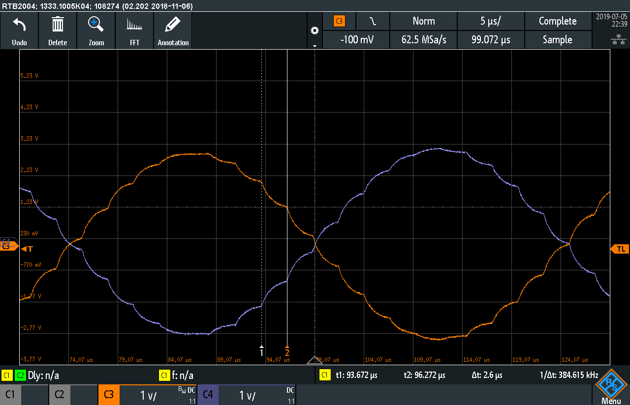
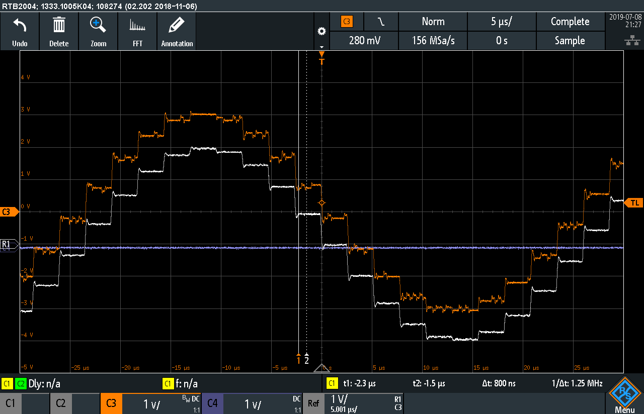
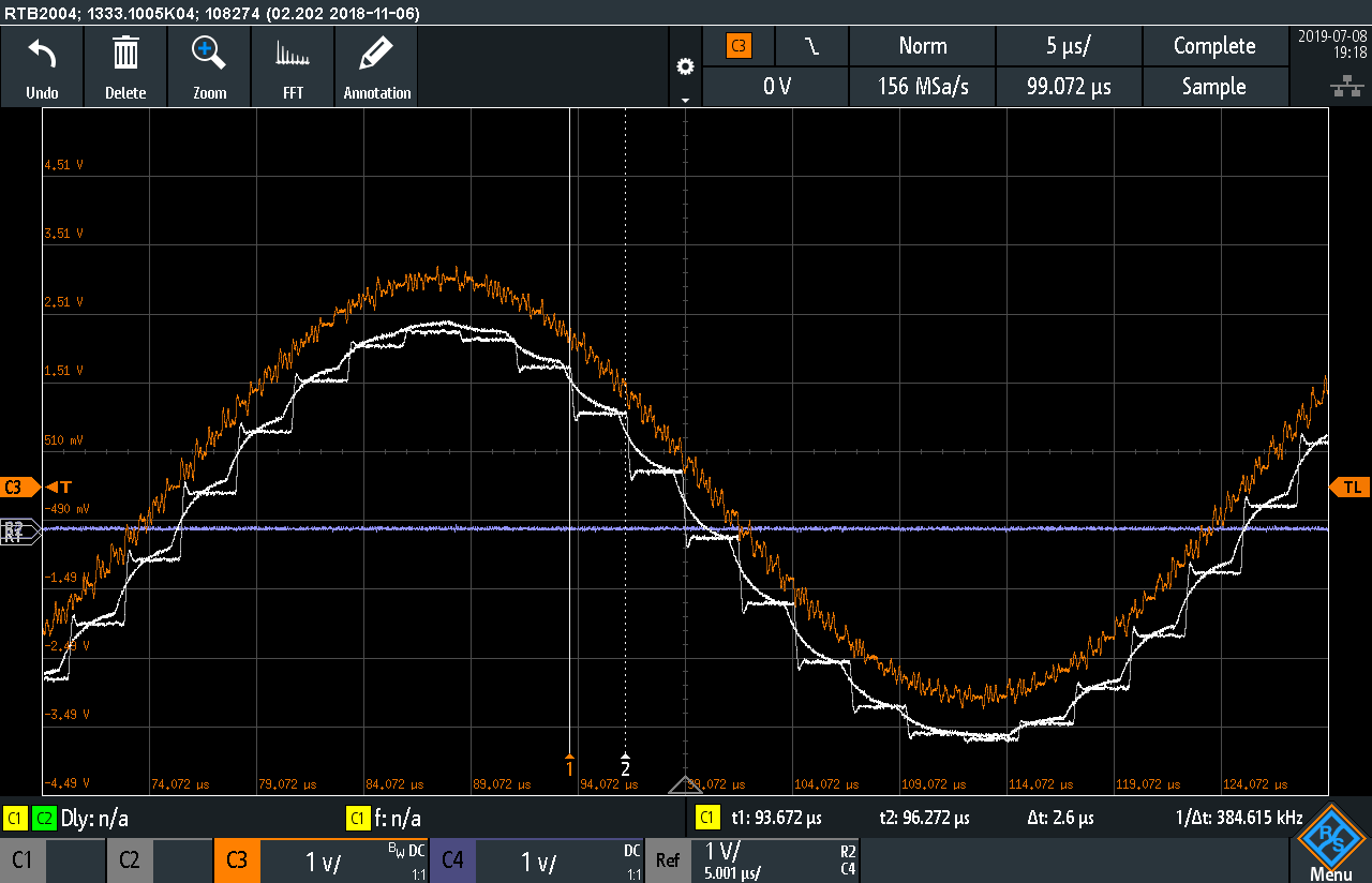
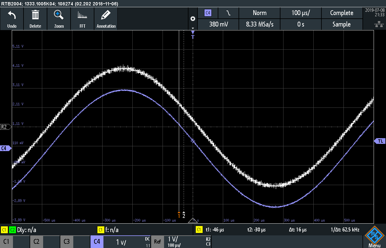
I have however discovered that while at 1kHz (any sample rate) the waveform clocks in a respectable 0.002% THD+N and looks smooth, the 20kHz is clearly stepped on scope trace  and the effect does not change if sample rate changed. this measures a whopping 1.3%. Picture attached of main signal (top) and THD residual (below).

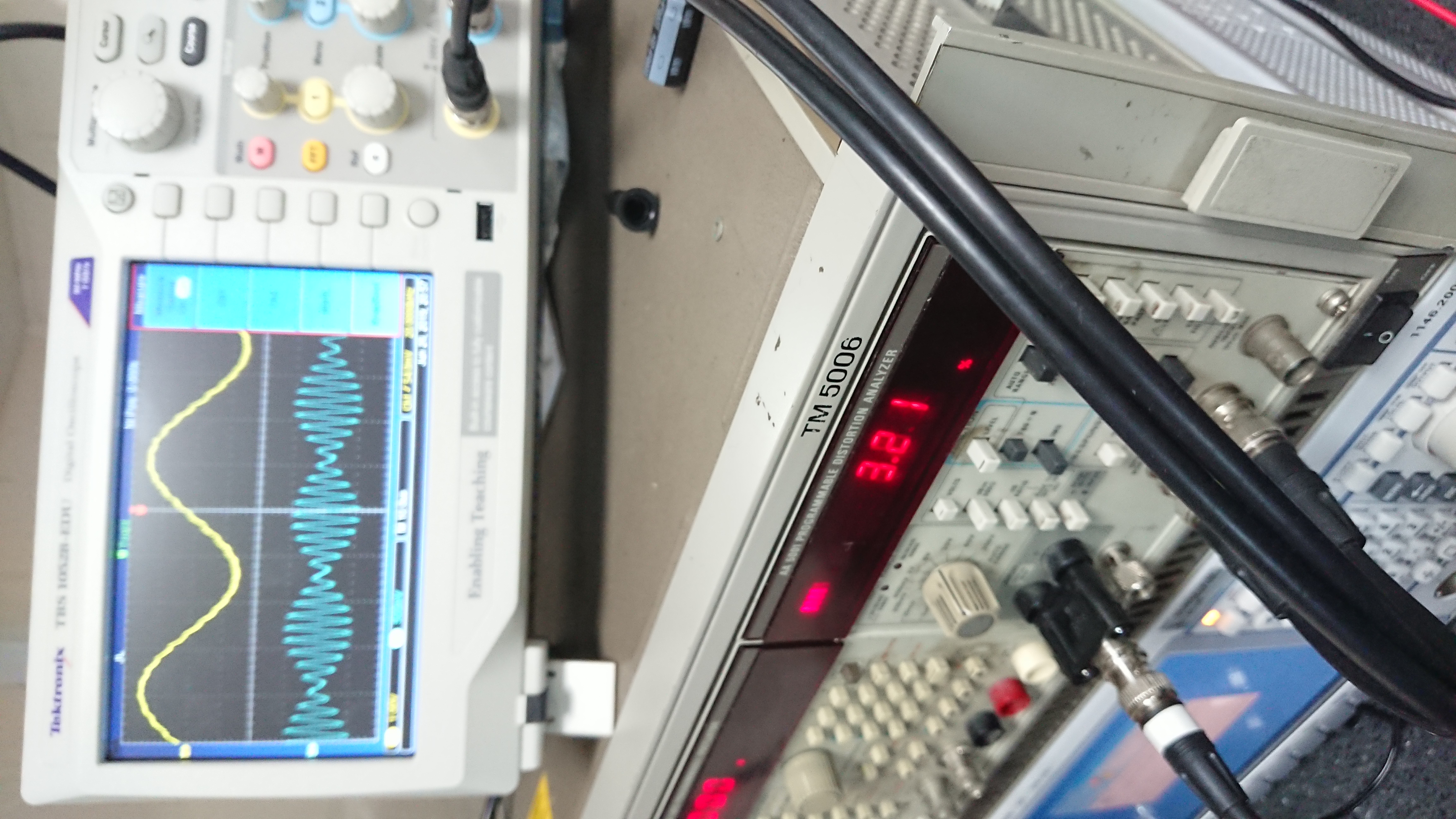
DAC from what I'm told is reset to "default mode". Changing filters therein made no difference.

Sample rate converter BCLK into DAC is 12.288MHz. SRC should be upsampling to 192kHz and in 24 bit.

If I put 80kHz filter in THD at 20kHz drops to 0.16% which is several orders worse than the spec sheet seems to suggest... 

The stepping is also not scope artefacts; I've tried another different design dac unit in same setup and this effect was not apparent.

Could you kindly advise?

Very best regards,

Simon.

  • Hi Simon,

    Can you confirm what you are using for SCK?

    When you say ''reset to default mode", do you mean there are no commands being written to the PCM? If there are any configuration commands, can you list them here?

    Thanks,

    Paul

  • Hi Paul,

    Thank you for taking up this enquiry

    SCK comes from 24.576 MHz oscillator module which is also shared with SRC MCLK.

    Default mode meant there are no commands written to PCM, that is correct.

    Very best regards,

    Simon

  • I accidently "muted" this thread but still interested in it....

  • Hi Simon,

    I think what you are seeing is normal.  The PCM5242 has an integrated interpolator which will up-sample any input to 384ksps.  If you are using a 20kHz sinewave as a input signal, then you will have about 19 samples per period.  I think you are seeing this now.  In audio products, we usually define and measure our THD+N specifications with an A-weighted filter.  This filter mimics the response of the human ear, and is a band pass filter of about 20-20kHz.  If you apply that filter with an audio measurement system, then you will see a much better THD+N number.  You could also lower the fC of the external RC filter to something closer to the audible band, maybe fC=24kHz.  This will smooth the 'steps' of the output.  The switching of the delta-sigma modulator occurs at about 16*384kHz, so it is removed in either case.

    This is a measurement I did on my bench, using a 192kHz input signal, and only the simple RC on the output.  You should see something similar.

    Thanks,

    Paul

  • HI Paul,

     Thanks for your informative response.

    I manufacture High end audio product so I do need low distortion at higher frequencies than normally stipulated.

    I also need to reproduce up to 80kHzsignals to match various High definition and above requirements (192kHz max sample rate in mind for this design).

     I'm used to using previously the PCM1792/6 which never showed these artefacts even unfiltered, but under same setup?

    Should I have used the Antialiasing gyrator circuit (SBAA001.pdf) with this then?

    It seemed from both data sheet and application note that this was not necessary...

    Very best regards,

    Simon

  • Hi Simon,

    I think it is important to understand the differences between the two DACs: PCM1792 and the PCM5242.  Both of these devices feature a delta-sigma current segment modulator, but with different digital fitlers and modulator architectures.  The PCM1792 features an 8x interpolator, while the modulator runs at 64x the original sample rate.  The PCM5242 has a variable interpolator that will up-sample to 384kHz regardless of the input sample rate (within limits).  It's delta sigma modulator runs at a much higher frequency, about 6MHz.  

    Consider the an experiment where I use the same 48kHz input sample rate for the both of the PCM devices with no external analog filters.  Both will effectively up-sample to 384kHz.  See the image below:

    The white line is the PCM5242 and the orange line is the PCM1792A.  You can see that they have the same amount of interpolator points per sine period (and quantization noise).  The main difference is that you can see the DSM switching on the PCM1792A.

    When you use a higher sample rate, this will look better on the PCM1792A:

    In this image, the white lines are the PCM5242 (one is filtered with the LPF, the other is not) and the orange line is the PCM1792A.  The sample rate is now 192kHz, so the PCM1792A is interpolating at 8xfS, and has a total oversample rate of 64xfS.  

    At low frequencies the benefit of the PCM5242 is more apparent:

    In this image the blue line is the unfiltered output of the PCM5242 and the white line is the unfiltered output of the PCM1792A. They both have a 192ksps input signal outputting a 1kHz tone.

    The switching noise of the DSM (or out-of-band noise) for the PCM179x family will start to increase at about 0.5×fS, but due to the architecture of the PCM5242, the out of band noise does not start to increase until about 200kHz, regardless of fS.

    All this to say that the selection of the DAC will be trade-off in either case.  Operating at 192ksps with a desired output signal at 80kHz may result in higher distortion on the PCM5242 with out filtering, but the out of band noise (and signal aliasing) will be difficult to remove on the PCM1792A.

    Let me know if this helps :)

    Paul

  • Hi 

    Yes I think you've just confirmed what I was suspecting.

    It looks like I will need to add opamp lo-pass filter similar to that used on PCM1792/6 applications.

    Very best regards,

    Simon