This thread has been locked.

If you have a related question, please click the "Ask a related question" button in the top right corner. The newly created question will be automatically linked to this question.

TAS5825M: Clock halt or auto-recovery occur OCP

Part Number: TAS5825M


Dear Sir.


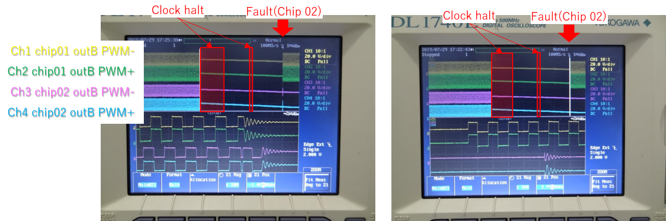
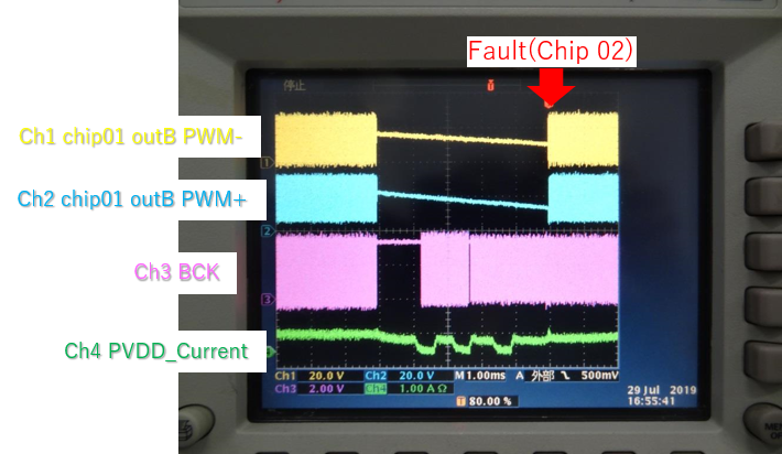
Our system breaks off  SCK and LRCK when changeing function or chpater.

During that, TAS5825 sometimes occurs OCP

  (register value: x70=01, x71=04, x72=00)


Couldd you reply below questins?

1. In the first place, Does TAS5825 support the system whose SCK and LRCK often break off?

2, When SCK and LRCK halt or auto recovery, does this device need to comply some kind of procedures?

    ex.) Timing among SCK,LRCK,DATA,

           During clock break off, they should fix  Low level or High level, or no requirement 

3.  MASK CLK_FAULT(Bit 4) of  PIN_CONTROL1 register (0x74) is set 1(MASK), in our system.

   Does this bit only control Fault pin, or  change the process for clock error (all channels into Hi-Z)?

4. Do you have any other advise for this issue?

  • hello,

      could you show us what is your PVDD and LC filter selection? better share us schematic to take a look.

    regards

    Linda

  • Hello,

    Thank you for your reply.

    PVDD is 24V and schematic is bellow.

    R4,R5,C5,C6 is Snubber circuit. and R2,R3,C7,C8 is Zobel fillter.

    (Out B is same schematic as Out A)

    I have one more question.

    5. After detection of OCP, in how long of a period does FaultZ pin output L?

      (datasheet shos that channel shuts down in <100ns aftre OCP)

  • Hi, 

    Some suggestions:

    1. Use FAULT pin to trigger, then capture current through the inductor and BLCK clk.
    2. Try to use 768kHz PWM switching frequency.
    3. Try to remove Snubber & Zobel to debug the root cause.

    Regards,

    Matthew

  • HI.

    Thank you for your suggestion.

    But, I'd like you to reply my questions firstly, especialy below two.

     >1. In the first place, Does TAS5825 support the system whose SCK and LRCK often break off?

    >2, When SCK and LRCK halt or auto recovery, does this device need to comply some kind of procedures?

    And, if possible, could you tell me why ddi you suggest the debug procedures?

    some of them will take time, so I'd like to know the aim of the suggestion.

  • HI, 

    When clock error happens, TAS5825 will mute device, then turn off driver to Hiz mode. After correct clock provided again, automatically unmute, then turn on driver into play mode.

    The debug idea is to firstly check the BCLK turn off transition behavior and inductor current. Normally higher PWM switching frequency / large inductor / without snubber & Zobel will decrease peak current.

    Regards,

    Matthew 

  • Hi

    Thank you for your reply.

    I captured BCLK and LRCK.

    The behavior is below.

       provide 48k --> halt --(1.2ms)--> provide 96k --(1.2ms)--> halt --(0.07ms)--> provide 48k --(2.3ms) --> Fault

    In response to this, I'd like to confirm below.

    6. Are there any requirements about minimum terms for clock providing.

         ex.) just after clock recovery, XX ms is required before next halting

  • Hi,

    Thanks for the capture. Your system clock changing is clear.

    Could you also help to measure the PWM waveform during FAULT happens? Whether PWM frequency drops a lot with 0.07ms clock halt? If so, it's highly suggested to detect FAULT status, once happen FAULT, then write I2C command to clear FAULT:

    w 98 00 00

    w 98 7f 00

    w 98 78 80

    Regards,

    Matthew

  • Hi.

    We set Bit4 (MASK_CLK_FAULT) of PIN_CONTROL1 Register (Offset = 74h).

    Clock error doesn't activate fault pin.

    PWM waveform is below.

       ch1,2: PWM of chip01

      ch3,4: PWM of chip02 (this chip occurs OCP)

  • Hi,

    Could you confirm there is no PWM output while providing 96kHz I2S between two clock halt? What's more, the OC FAULT still happens just after second clock halt? If so, it seems chip02 two high duty cycle PWM output at first 48kHz tune off cause OC Fault.

    One more point want to check is whether there is below script with your initialization script:

    w 98 00 00

    w 98 7f 00

    w 98 7d 11

    w 98 7e ff

    w 98 00 01

    w 98 51 05

    Regards,

    Matthew

  • Hi.

    >Could you confirm there is no PWM output while providing 96kHz I2S between two clock halt?

      No output. I think abut 2.3ms is required to output PWM after clock recovery

    > What's more, the OC FAULT still happens just after second clock halt?

      It seems that Fault occures the moment  which device try to re-output PWM.

    > If so, it seems chip02 two high duty cycle PWM output at first 48kHz tune off cause OC Fault.

      Actual output level should be low because Out+ and Out- look the same.

      I can't hear any sound from connected speaker at the time and PVDD current is not so high.


    I found that LRCK or BCK halt term is related to Fault ratio.

    10ms clock halt always occures OCP.

         Clock halt term     Fault ratio

           1 ms                       0/500

           2 ms                       1/100

           5 ms                       1/10

         10 ms                     10/10

         20 ms                     1/10

         30 ms                      0/500

         40 ms                     0/500 


    Could you confirm this symptom?

    And could you advise about countermesure?

  • Hi,

    The rough idea of different clock halt measurements result is different output voltage while TAS5825M wants to back to play mode after correct clock recovery. The large duty cycle PWM means lower switching frequency, which will cause larger inductor ripple current.

    More hints are to remove Zobel circuit and measure the current through the inductor to check whether there is large OC current. Another option is OC FAULT will pull low FAULT pin even clock error is ignored, so it can be used for SOC to clear FAULT, then TAS5825M will be back into play mode again.

    I will collect your measurements and discuss with design team. This E2E thread is going to be closed, and more details are aligned through email.

    Regards,

    Matthew