This thread has been locked.

If you have a related question, please click the "Ask a related question" button in the top right corner. The newly created question will be automatically linked to this question.

PGA2500: How to select resistance for limiting the input current of PGA2500

Part Number: PGA2500
Other Parts Discussed in Thread: NE5532

Hi Sir,

We are going to select PGA2500 and NE5532 in our application. In PGA2500 evm sch(sbou023.pdf), there are Resistors R7 and R8, along with Schottky diodes D6 through D9, provide input protection for the PGA2500. We confused the selection of R7 and R8. Since we use 10 ohm(0603) in our application, the resistors  always blow. Pls give us some recommendation on this issue.

Thanks.

BR 

Sara 

  • Hi Sara,

    Yes, the resistors R8/R9 are used to limit the current to the Schottky diodes; and their power rating must be able to withstand the maximum current in the fault condition. 

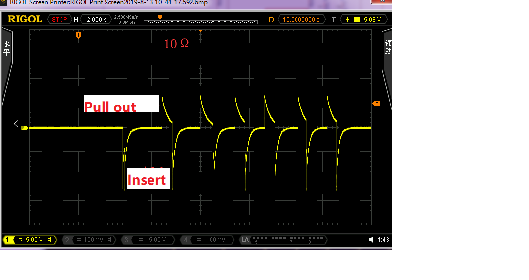
    For example, one common scenario is when the user shorts the microphone cable and/or input connections.  In this case, a transient of current occurs as the DC blocking capacitors (10 to 47uF) discharge the Phantom Power voltage (up to ~48-V), and a fast transient current surge flows through the resistors and Schottky diodes.  In the case of a 48-V phantom power, the current surge will be exceeding 4-amps flowing through the resistors for a short duration of time

    1) Can you describe the fault condition occurring in this application that is causing the resistors to blow up?  Is it similar to the one described above? If the fault condition is different to the above, what is the worst case over-voltage that the device can see at its inputs on this application? Is the fault a DC overvoltage condition or a transient?

    2) Is there a Phantom power supply used in this application? If yes, what is the voltage level? What size of DC blocking capacitors are used in this case?

    Thank you and Best Regards,

    Luis


  • Hi Luis,

    Thanks for your reply.

    1) Can you describe the fault condition occurring in this application that is causing the resistors to blow up?  Is it similar to the one described above? If the fault condition is different to the above, what is the worst case over-voltage that the device can see at its inputs on this application? Is the fault a DC overvoltage condition or a transient?

    -- When gooseneck mic is inserted or pull out.

    2) Is there a Phantom power supply used in this application? If yes, what is the voltage level? What size of DC blocking capacitors are used in this case?

    --48V iaccord antecedent. the DC blocking capacitors is 47uF/63V.

  • Hi Sara,

     The user should turn-on the 48-V phantom power after all the microphone connections are made, and avoid changing the microphone connections after the 48-V phantom power is turned on.  As mentioned in the datasheet, the series resistor will be see a  large surge of current if the input connections are shorted after the AC coupling capacitor is charged to 48-V. 

    A possible solution is to increase the resistor to 50-ohms (if possible, use a larger package, higher power rated resistor).  In addition, please add a ~11-V clamping TVS bidirectional diode at the other side of the series resistor.

    Please see below. 

    Thank you and Best Regards,

    Luis

  • Hi Luis,

    Thanks.Would you give me some recommendation on selection of C1 & C2. Because  we can hear stridulation when  gooseneck mic is inserted or pull out. after the 48-V phantom power is turned on. We know it is rule-breaking operations, but we can not avoid this risk, how we  decrease the stridulation volume.

    Thanks,

    BR

    Sara

  • Hi Sara,

    The 48-V phantom supply voltage will charge the 47uF DC blocking capacitors, and when the inputs are shorted, this will produce the large surge current. 

    You may consider reducing the value of the blocking capacitors.  The PGA2500 recommends a capacitor value in the range of 10uF to 47uF.  The DC blocking capacitors interact with the input impedance of the PGA2500 (4600-Ohm typical per pin), forming a high-pass filter, blocking the DC signals.  When using 47-uF DC blocking capacitors at the inputs, the corner frequency (f-3dB) is ~0.747-Hz.

    f(3dB) = 1/(2*PI()*Cin*4600-Ohm) = 1/(2*PI()*47-uF*4600-Ohm) = 0.747-Hz

    Similarly, using 10-uF DC blocking capacitors will set the corner frequency to ~3.51-Hz.  

    If your application allows for using a higher corner frequency on the high-pass filter, you could consider reducing the capacitor further to reduce the current surge/voltage spike.  The trade-off is the higher corner frequency on the high-pass  filter, that will result on the attenuation of  the low-frequency signals.

    Thank you and Best Regards,

    Luis