This thread has been locked.

If you have a related question, please click the "Ask a related question" button in the top right corner. The newly created question will be automatically linked to this question.

Need a suitable Class D amplifer for transformer application

Other Parts Discussed in Thread: TAS5760M, TPA3220

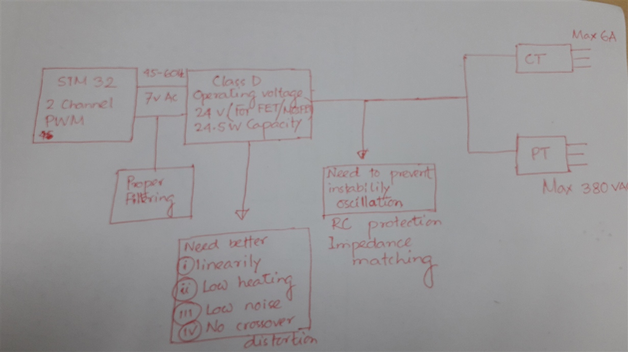
My intention is to make an 3-phase power calibrator !

Similar to this link, https://us.flukecal.com/products/ele...wer-calibrator

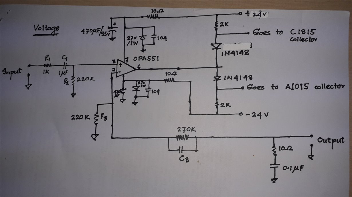
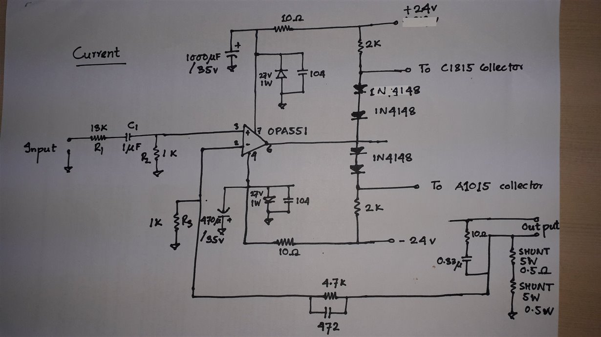
My current AMP design might be class AB type. 


I am not worried to much about PWM generation ruther I am thinking how can I move class AB to Class D amplification.


A lot of the design effort relates to maintaining linearity and avoiding crossover distortion.


2  amplifiers( current, voltage)  output will feed to CT and PT! Lets consider load will be connected in their output!


REQUIRMENTS :


1. The amp input  should be  plus and minus 7volt AC, 45-65Hz( 1 Hz has been converted to 1024)

2. Amp operating voltage should be more or less 24v.


3. 2 channel signal (not sure PWM) should be use , one for current, one for voltage.


4.Can run current transformer(input 16.5 V/1.5 A)  and potential Transformer (input15v/2A). PT output may be 15VAC.

5. If possible both voltage and current amplification is required in one IC.

6. Both positive and negative half signal should be amplify. ( take a look bellow 


For CT, current transformer primary winding has 80turns, 16.5 V/1.5 A, secondary has 20Turns, 4.125v/6A output!
For PT, Potential transformer, Primary has 80turns, 15v/2A rating input, secondary has centertap!
At secondary 960turns, 360v/0.332 A and 960turns 180v/0.166A output.

I am using TIP147, TIP142, C1815, A1015. They are properly biasd like cascaded 3 stage, may be AB class network. More symmetric way, like one pairs AB class output is connected to others pair. Last pairs base is connected to first pairs base! At last a voltage divider of 5 ohm has been made between 2nd and 3rd outputs!

Hope you wll find a solution soon.


Hasan

  • hello Sir,

       as this is one duplicate thread as another one which had been under our support thread. I could close this thread and follow up by another thread.

    Regards

    Linda

  • Hi Hasan,

    What about TPA3220(analog input), or TAS5760M(digital input, I2S)?

    In my understanding, you will connect the Speaker+/- to the primary side of transformer, right?

    Regards,

    Hao

  • Hi Zhang,

    Thanks for your recommendation.

    My application is not for Sound speaker .

    The ClassD output will be fed primary side of the transformer with proper short circuit protection and technique.

    Keep in mind that my current and voltage amplification for CT  and PT should be (16.5 V/1.5 A) and (15v/2A) respectively.

    So, ClassD's supply voltage should be 24 v or more range.

    My input signal 7v AC, 45-60Hz comes from DAC 8812 .

    So, its kind of low frequency application.

    Let me study your datasheet first.

    I will get back to you soon.

  • Hi Linda,

    Thanks for respond here.

    For the time being lets also disscuss a issue,

    1. Low frequency and high frequency phase shifts caused by a transformer will occur if the transformer is inside the negative feedback loop (when the output of the transformer provides the negative feedback). Then the amplifier must be compensated for these phase shifts.


    2.  A product with a Class-D audio power amplifier (APA) driving an output transformer with inadequate low-frequency performance may shut down when its output is stepped from zero to maximum at the start of a sine cycle. Shutdown is triggered by short circuit protection (SCP), after the first half cycle of the sine output. The root cause is saturation of the transformer core.

  • Hi Hasan,

    Yes, I understand you point. I mean the Speaker+/- in audio application will be connected to the primary transformer in your application.

    I've also taken your requirement into consideration. You may take a look at the parts first. Thanks!

    Regards,

    Hao

  • Looking at your suggested TPA3220 EVM,

    How would you connect such 60Hz step up transformer ?

    Should it  be H-bridge or BTL !!


    LC filter is visible here! in my case the primary side impedance is 0.00117ohm.

    People says , Audio amp can usable for 2- 16ohm load!

    While it was connected to Class AB output , a 10 ohm along with 0.33uF in series RC filter was connected parallay to primary.

    Looking at the datasheet "PWM frame rate selectable for AM interference is in kHz range "


    Does it compatible ?

  • Hi Hasan,

    Transformer terminals should be connected after the LC filter. That's why I thought the transformer here is something like a speaker in typical class D audio amp application. What you want to do is generate a tens of Hz signal to drive the transformer, right? You can put a cap in serial with primary transformer to block the DC signal.

    "PWM frame rate selectable for AM interference is in kHz range " is talking about the switching frequency within the closed loop. The amp switches at this frequency to maintain the audio output.

    Regards,

    Hao

  • Hi Hao,

    Beside this idea, we need to think what would be  the loading effect / impedance effect if we use 60Hz step up transformer insted of speaker!

    This smart IC can also provide shot circuit protection internaly may be. Keep in mind that 15 v amplified signal need to conduct full cycle to trasformer primary side.

    Meanwhile same as PT, how about CT ? My classAB feedback  CT amplifier"s gain was different than PT. RC filter' s high frequency gain was  rejected.

    I need to run both at a time.

    Kindly figure out " current mode ClassD" also.

  • Hi,

    Agree with you. Transformer is different with speaker. For this kind of closed-loop class D amp, the amp is always trying to regulate the voltage across the speaker+/-(transformer terminals in this case) referring to input signal.

    We do have current limit and also over-current shut down feature.

    I didn't find a solution for the current loop. This is because our amp takes the voltage across the output as feedback, and then regulate the same voltage. Probably we need a way to feedback the current and convert it to the voltage sensed by the device. I haven't found a way yet...

    Regards,

    Hao

  • Thank you once again !

    We could face challenges  for using CT in this system.

    Right at the moment it looks like "PT can be manageable with this circuit.

    For the PT, an audio expert says, "A transformer causes a phase shift at low frequencies caused by its inductance. The phase shift is reduced at low frequencies if its size is increased."

    Another engineer said " Class D amplifiers approximate voltage sources, they won't take kindly into a CT load."

    This class-D audio amplifier IC is smart. It has current limiting and high temperature shut-down.

    But for my electrical application I probably want to select the amount of voltage produced by my current transformer and its shunt resistance.

    So select a class-D amplifier IC that produces more current than I need and I will connect  shunt resistor to its negative feedback input if it has one.