This thread has been locked.

If you have a related question, please click the "Ask a related question" button in the top right corner. The newly created question will be automatically linked to this question.

Noninverting or inverting Op Amp vs Noise

Other Parts Discussed in Thread: OPA211, OPA2132, OPA2134, OPA1611

Grettings everyone!

Recently I have designed a microphone preamp and bit-by-bit got deeper under the hood of op amp problematics I was completely unaware of before. As a result, I have read many interesting papers regarding noise topics and op amps, including some datasheets from TI opamps that helped a lot. I am familiar with some statistics and probability topics, so figuring that part wasn't hard for me. I even compiled a Google Spreadsheet with several different methods for noise calcs for quick comparisons and here we get to my first question:

1) What method is most accurate? First two methods are from TI's datasheets for OPA2134 (OPA2132) and OPA211 (OPA1611), while third is derived from a paper I found on the web by Kenneth A. Kuhn (reference url links are provided in the spreadsheet). There is a high consistency in the calculations results from TI equations and almost -5 to -10 dB (!) worse results for S/N ratio using Kuhn's approach. Can you tell me why? Both methods seems to calculate noise from Rs, Rg and Rf the same way, but substantial differences come from current and noise modelling (especially for current noise in Kuhn case).

2) Simulating or calculating manually? To make a problem more confusing, when I run simmulations of OPA1611 for both inverting and non-inverting topologies in TINA, I get considerably higher total output noise for inverting and non-inverting topologies (almost 3x) then calculated using TI equations. Can you tell me why? What am I missing here, since in TINA there must be something that adds additional noise to the output I am not calculating in the spreadhseet. I did read Arthur Kay's papers over at en-genius.net about often wrong spice models of op amps when it comes to noise simulations, but since these ops are new devices, I would rather assume they are modeled right (?)

3) From this analisys, inverting topology is slightly better then non-inverting. Correct?

Calculation / Simulation results: 

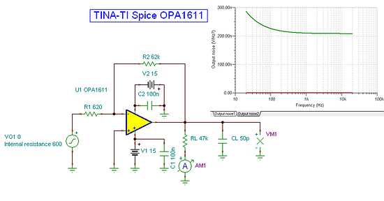
TINA OPA1611 inverting op amp simulation
R source = 600 ohms
R1 = 620 ohms
R2 = 62 k ohms
simulated output noise = 210 nV/root Hz (or 29.7 μV at 20kHz bandwidth)
calculated output noise using TI equations (spreadsheet) = 16,95 μV

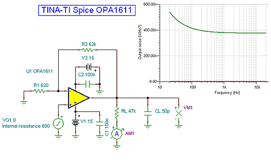
TINA OPA1611 non-inverting op amp simulation
R source = 600 ohms
R1 = 620 ohms
R2 = 62 k ohms
simulated output noise = 390 nV/root Hz (or 55 μV at 20kHz bandwidth)
calculated output noise using TI equations (spreadsheet) = 21,71 μV


Well, this is the end of my post - thanks for reading :)
I hope someone at TI can help me resolve this issues and also be useful for someone with the same dilemmas. Thanks!

  • Darko,

    You've asked interesting questions. Please allow me to make some observations that may help to focus the discussion.

    Are you making a microphone preamp that would be used with a variety of types of microphones? If so, you will surely want a non-inverting input stage. Pro-type microphones are intended to be rather lightly loaded. Typical input impedance of a microphone input stage is a few k-ohms or higher. The inverting amplifier's input impedance is determined by the input resistor, 620 ohm in your case. This input impdedance significantly loads the output of the microphone. Another way to look at it is that the effective gain of the amplifier is reduced by the microphone source impedance. The effective gain of your inverting amplifier is about half that of the non-inverting amplifier because the source Z of 600 ohms combines with the input resistor to set the gain. So while the output noise of the inverting amp is approximately half that of the non-inverting amp, the output signal is approximately half, also. Thus, there is no real S/N noise advantage. If you adjust the input resistor to achieve equal signal gain, you will find that the noise is nearly the same.

    There is another effect that comes into play. With the inverting configuration, the current noise of the inverting input reacts with the series resistance of the input resistor plus the source resistor. This doubles the input bias current noise contribution to the total noise. When the 600 ohm source resistance is moved to the non-inverting input, the current noise contribution at that input is uncorrelated to the other input and adds 3dB less to the current noise contribution.

    I hope these points will add some clarity. If you can provide more detail on your application I may be able to help optimize it.

    Regards, Bruce.

  • Thank you Bruce for your reply. It cleared all the confusion regarding preamp design and restored my confidence in prior knowledge.

    I purposely ommited input impendance and gain variations in my first post, to avoid overvelming information in the start. Because minimizing input noise was my main goal, I completely forgot in my post the input impendance factor. Another moment that contributed to that confusion was another simulation in TINA (AC transfer characteristic) regarding gain reduction effect (the lack of) in inverting stage -- what I realize now is the wrong schematic approach I took. I've set the source input impedance to 600 ohms as can be seen on above pictures, barely though, but in inverting topology gain was not affected no matter what Rg was set (from 6 to 6M ohms). Now, thanks to your post, Bruce, I realize why - it was a faulty schematic modelling - I should add Rg outside the generator, not via internal properties page of the input generator. I beleived TINA will automatically use reference points for gain directly at 'generator nodes' without Rg. That is why I changed the spreadshet to reflect 'ideal' inverting op amp with gain of 100, instead of around 50 and that resulted in false better S/N ratio of an inverting topology. That was a moment I got confused and decided to ask for your help.

    My first prototype was, in fact, non-inverting, exactly because of the things you mentioned. It is not a universal model, it is specifically designed for a particular mic model, since another type (condenser) usually requires fantom power and I wish to separate them.

    edit: there still is a question of difference regarding spice simulation, but logically I'll assume that result is wrong.

    Again, thank you Bruce very much!

    Regards,
    Darko

  • Darko,

    Now that the basic issue is cleared up, I'll make an additional comment:

    Using the OPA1611, you could further reduce the noise. The resistance of the feedback components could be reduced to say 200 ohms and 20k ohms. This would reduce the thermal noise contribution from the resistors and the input current noise contribution of the amplifier. This would make a minor improvement with a 600 ohm source impedance. The improvement would be much more significant with lower source impedance.

    Regards, Bruce.

  • Thank you Bruce, I thought lower resistance values could compromise stability or increase supply current (which I am not much concerned for), but I will take your advice.

    Thank you for your kind help.

    Darko 

  • In order to conclude this topic, I will just add a final note: I realised the differences in noise calculations from TI datasheets and another method presented in my first post. By closer examination of the equations I acctually overlooked the fact that TI formulas sum noise density figures, not RMS voltages I assumed at a first glance. Thus I miscalculated Rs/Rf/Rg noise contributions which yielded much lower total output RMS noise using TI equations. I have corrected this error and got pretty consistent results that go along with TINA simulations.

    Darko