


The design uses the dual BTL (M1 = 0, M2 = 0), and it is a revision ("second generation") of a previous design that was working ok.
This is the partial schematic (most of the decoupling network not shown; but it is essentially identical to what's suggested in the datasheet):
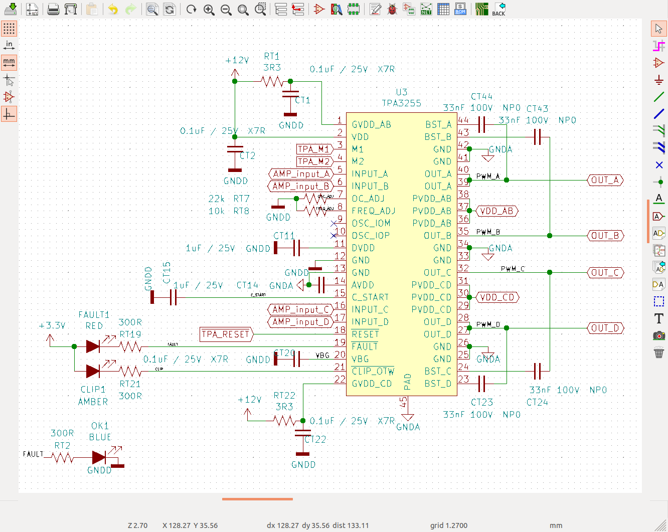
(notice, RT7 is the OC resistor, I set it to 22k; RT8 is the FREQ_ADJ resistor, set to 10k for AM2 — 600kHz — PWM frequency)
I'm applying 30V to all PVDD voltages, and a 12V wall adapter (producing 12.1V as measured at pin 2 of the TPA3255).
I confirmed (via test points) that M1 and M2 are both set to 0.
The symptoms:
The output activates and produces exactly 10 pulses (i.e., if I look at one of the output pins; e.g., OUT_A) before it shuts off. The frequency is dead-on: 6 pulses in exactly 10 μs. At the time that the output dies, FAULT is asserted, just for a little while. The process repeats maybe every 100ms or 200ms? (I can see the FAULT LED blinking more or less fast)
The output does not seem shorted. I check with an ohmmeter, and I get: between either one of the outputs (OUT_A, B, C, or D) and GND, approximately 250 kΩ; between OUT_A and OUT_B, approx. 700 kΩ; same thing between OUT_C and OUT_D.
At first, the output had no load whatsoever (in the design, the LC output filter is on a separate board). I connected a light resistive load just in case (200 Ω between OUT_A and OUT_B, 200 Ω between OUT_C and OUT_D). Did not change anything.
Additional "debugging information/hints" I measured:
- Voltage at OSC_ADJ pin: 1 V
- Voltage at FREQ_ADJ pin: approx. 0.8 V
- Voltage at C_START pin: 0 V
- Pin 2: 12.1 V
- Pin 1: 10.55 V
- Pin 22: 11.5 V
- Pin 11: 3.31 V
- Pin 14: 7.82V
Any ideas of what else I should try / measure? (or in any case, anyone recognizes the symptoms and can guess where the culprit may be?)
Thanks,
Carlos
--
