This thread has been locked.

If you have a related question, please click the "Ask a related question" button in the top right corner. The newly created question will be automatically linked to this question.

TPA6120A2: TPA6120 gain issue

Part Number: TPA6120A2

Hello.  I'm running the TPSA6120 in an audio application.  I'm looking for a gain of 2.  I've configured it according to Figure 16 AND Figure 14 in section 10.2 on p11 in the datasheet. Unfortunately I'm seeing a slight loss instead of any gain.  I've tried 1K, 2K, and 4K values for the Rf's.  I've tried 50, 100, 150, and 1K values for Ri's. 

The gain loss occurs whether it's under load (8 ohms all the way up to 150 ohms)  or completely disconnected from any load.  So for example, if I feed it a 1v signal, my output is roughly 0.8 volts instead of the 2V I would expect to see.  What am I missing here?

  • Hi, Matt,

    Welcome to E2E and thank you for your interest in our products!

    Excuse me, could you provide your entire TPA6120A2 schematic portion, please? This would be useful to have a better approach to the issue.

    In addition, could you provide a scope capture of the differential input and the output? A 1KHz sine wave could be useful.

    Any other information you could provide will be appreciated.

    Thank you.

    Best regards,
    Luis Fernando Rodríguez S.

  • Thanks for your reply, Luis.

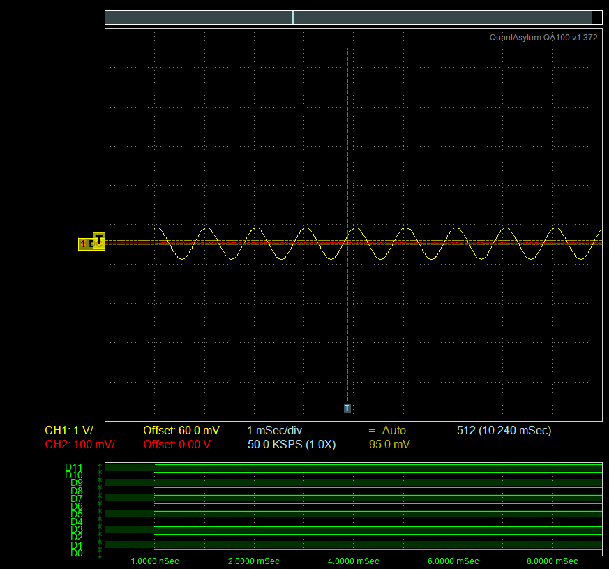
    Here are the input and output signals.  This is a 1V 1kHz sine wave at the input.

    Here is the output:

    Give me a few minutes and I'll upload the schematic.  It's basically a copy of the schematic in the datasheet that I posted earlier.

  • Here is the schematic.  I've tried everything from 50 ohm input R's to 1K input R's.  I've also tried changing the feedback resistors, I've used 1K's, 2K's, and 4K's.  I've also tried running it as singled ended input by disconnecting R20 from the audio path and shunting to ground.  It doesn't matter what I do, nothing increases the gain.

  • Hi Luis

    Any thoughts on this?  I'm running the power at +/-15vdc.  The issue happens across multiple TPA6120's and multiple PCB's.

    I've exhausted every angle I can think of, I can't seem to get any gain out of this chip.  It sounds fantastic in the application, but as it stands it doesn't produce enough volume to meet our required spec.

    One thing I notice--the information regarding gain in the Evaluation Board datasheet differs slightly from the TPA6120 datasheet.  I configured the chip based on the Eval suggestion for non-inverting single-ended input mode.  Doing it this way I get the required gain of 2 at the INPUT of the TPA, but no signal at the output.  Again, this happens across several different PCB's with several different TPA chips.

    Please let me know your thoughts; if we can't solve this issue I'll have to move on and change the design.

  • Hi, Matt,

    I apologize, for some reason I didn't receive the notifications from your replies.

    I took a look at the schematic that you attached in previous responses. But it seems that both inputs are tied to the same input signal. Have you tested a differential signal at the input? 

    Thank you.

    Best regards,
    Luis Fernando Rodríguez S.

  • Yes, I'm using the old fashioned resistive isolation trick used with opamps.

    I have not tested with a balanced (differential) signal.  But I have tried running it in single ended input mode, just like Fig 14 from the datasheet.  See attached example.

    This configuration makes no difference--I still get no gain.  In fact, I can simply remove the IC altogether and still see the exact same signal level.

    Just to be clear, I have pin 1 tied to V- and pin 3 tied to V+.  Pin 2 is output, pin 4 is + in and pin 5 is - in.

  • Hello Matt,

    1)

    matt newport said:
    This configuration makes no difference--I still get no gain.  In fact, I can simply remove the IC altogether and still see the exact same signal level.

    If this refers to Fig 14 in previous post, then removing the IC should result in no signal on the output.  This suggests a lurking short somewhere in your prototype. (stuff like this happens to me! :)

    2) Regarding the schematic you attached: as Luis pointed out, with the inputs (R18 & R20) connected together the gain/topology is very different from the Figure 16 circuit.  IOW, apples vs oranges in terms of expected gain.

    Hope this helps.

    David

  • David McRell said:
    If this refers to Fig 14 in previous post, then removing the IC should result in no signal on the output.  This suggests a lurking short somewhere in your prototype. (stuff like this happens to me! :)

    Thanks for the reply, but it refers to Fig 16. My post wasn't very clear, sorry about that.

    If I remove the IC when it's configured like Fig 14 there's no output at all.

    I'm only running 1/2 of the IC, the other half is unused and unpowered.  According to the datasheet, this shouldn't matter...should it?

    This really has me frustrated.  I've poured over every aspect I can think of; pcb shorts, traces that don't actually connect, etc.  

  • matt newport said:
    I'm only running 1/2 of the IC, the other half is unused and unpowered.  According to the datasheet, this shouldn't matter...should it?

    per datasheet,...

    "11.1 Independent Power Supplies
    The TPA6120A2 consists of two independent high-fidelity amplifiers. Each amplifier has its own voltage supply,
    allowing the user to leave one of the amplifiers off, saving power, reducing the generated heat, and reducing
    crosstalk."

    So, I agree that it should not matter.

    Going back to Figure 16 and the schematic pic you posted... Figure 16 != your schematic.

    Does Figure 14 config work for you? (even if only for troubleshooting purposes?)

  • Neither configuration works for me.  I configure for a gain of 2, but they both give me the exact same output of <1.  This happens whether it's under load or disconnected from load.  Load is about 80 ohms.

  • David McRell said:

    Does Figure 14 config work for you? (even if only for troubleshooting purposes?)

    Neither configuration works at all.  By this I mean that I never, under any circumstances, am able to get a gain of 2.  I only see gains of <1.  This is across 10+ different boards and multiple IC's. 

    I'm convinced at this point the chip isn't actually doing anything and the audio is simply passing through the input/feedback resistors.  Is there a reason that the chip wouldn't come up when power is applied? Like some kind of condition that would cause failure or shutdown?

    I'm just trying to cover every base I can think of.  I measure -16 at pin 1 and +16.5 at pin 3, so I'm not exceeding the max voltage rating of 33v.  Inputs are pins 4 and 5, and output is tied to pin 2.  I've got continuity between each pin and its respective resistor or power connection.  There are no shorts or DC offset.  I've gone over every single detail that I can think of.

    I'm happy to post a pic of my board layout if needed.

  • matt newport said:
    I measure -16 at pin 1 and +16.5 at pin 3, so I'm not exceeding the max voltage rating of 33v.

    Based on everything else, this might be the underlying problem.    -16 and +16.5 is only a mere 0.5V under the absolute maximum rating of the part.  If turning on the power supply to pins 1 or 3 has any overshoot, the TPA6120 might exceed its absolute maximum killing the amp.

    I would recommend setting rail voltage to no more than ±15V (as recommended by TI), replace the TPA6120 on one of your boards, then apply power to the TPA6120.  Just to be on the safe side and for troubleshooting sake, set the rail voltage to a much lower voltage, like ±10V and then test.

    If your design requires 16V rails instead of 15V, you might need to reconsider the amp.

    Hope this helps!

  • Thanks for the suggestion. There's no overshoot on the power rails that I've measured. 

    I'll try replacing the part, and powering from +/-12 to see what happens.  I'll post results here.

  • Looks like this was the cause. Using +/-12v gives me the gain I need for the application, so I'm assuming I was blowing the chips every time at power up.

    I'm really surprised that this caused damage to the part.  In my situation, there's no overshoot on any of the power rails, at least nothing that I've ever measured. You might consider changing the datasheet to 30v max instead of 33.