A related question is a question created from another question. When the related question is created, it will be automatically linked to the original question.
If you have a related question, please click the "Ask a related question" button in the top right corner. The newly created question will be automatically linked to this question.
This only affects some delays when system power up. So it can still be connected to the mute (Pin12), Is it right?
Because I have made a lot of goods for the customer, now the customer have to rework on site. because they said the board can not pass ESD. All rework costs are bared by us. The problem for the customer is that this pin12 cannot be connected to GVDD by 100K resistor.
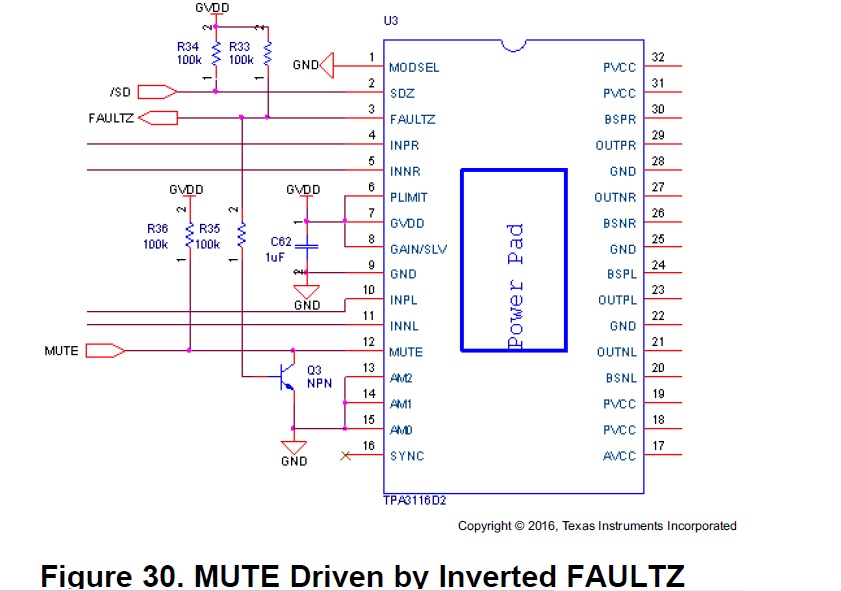
But I checked the IC datasheet, I saw the Pin12 can connect to GVDD by 100K resistor on page18. please see attached picture.
I need to know the Pin12 can connect to GVDD, and also connect to PVDD?
We should make sure that the MUTE pin is available when power-up.
For the recommended design of the figure 30, because the Fault pin is power-up to AVCC, so the MUTE is high when power-up.
GVDD is generated by AVCC. If MUTE is connected to GVDD directly, GVDD need some time delay to be stable when power-up. So connecting MUTE to GVDD, device can not be MUTE when power up.
The customer don't need mute function(no other control, this board is only audio amplifier). so if my circuit has problem(mute connect to GVDD)?
Now customer asked us to modify the circuit, put the Pin12 connect to Ground directly. How do you think? if the Pin12 connect to ground, will there be other problems?
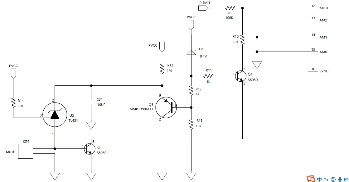
For the TPA3116 circuit, I only refer to other mute circuit. so I don't know this mute how to work?
Can you help me to analyze the working principle of this mute circuit? How do these parts(transistor and TL431) work?
SIP2 is mute jumper, if this jumper connect to ground, the amplifier don't work. please see attached mute circuit.
If I remove all components of mute circuit, only connect mute (Pin12) to ground. Is the function OK? I worried POP noise when start up power or power off