


Hi team,
my customer would like to use LM4951. Then I got some question.
Could you give your advice?
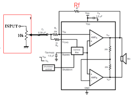
1. The customer would like to use single-ended. To use for single-ended, the customer should add coupling capacitor. Is this correct?
2. If yes, could you tell me the recommended capacitor value and schematic?
3. The customer plan to use valuable resistor on input as below picture. Would it be ok to use? If there is any issue for gain of amp, please let me know.
Regards,
Yoshi


