This thread has been locked.

If you have a related question, please click the "Ask a related question" button in the top right corner. The newly created question will be automatically linked to this question.

TPA6120A2: Further assistance with my AC Frequency Signal, please?

Part Number: TPA6120A2

Dear Ivan,

I measured the AC voltage from my soundcard just before the connection to my coil setup at 7.19volts.


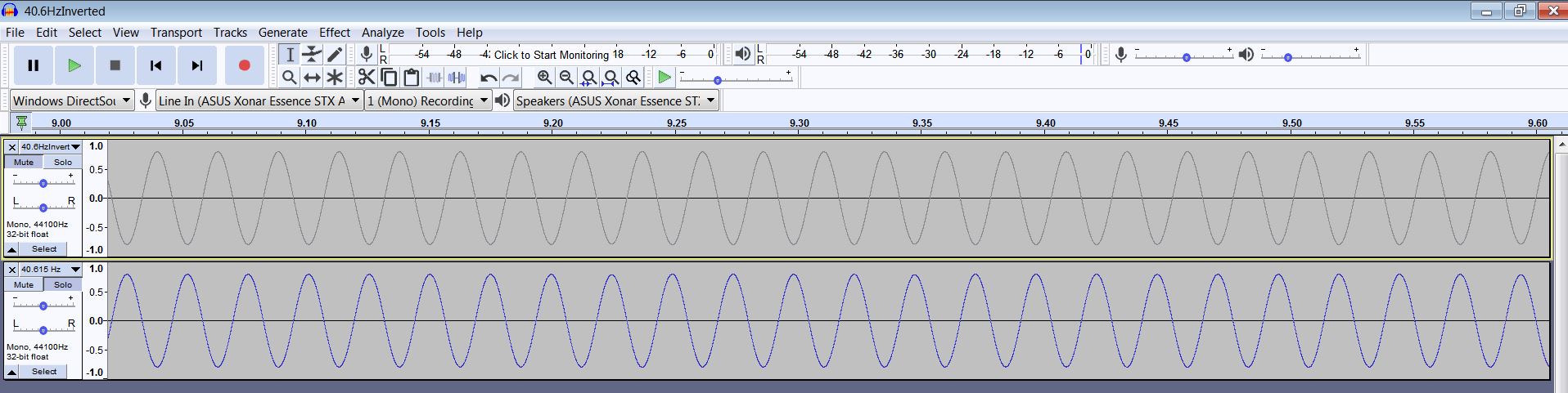
My setup at the moment comprises a frequency generating circuit which opens and closes a switch for my speaker connection at 500Hz +. Thus my sub 100Hz frequency from my sound-card oscillates at this higher frequency.


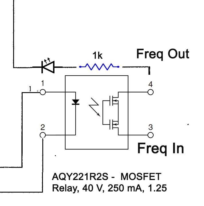
My frequency generating circuit originally controlled a 15v DC supply and to enable me to visually see if the connections to my coils were good, it has a 3.3volt LED in series with a 1k resistor.


Thus my 7.2v AC signal is passing through the 3.3v LED in series with the 1k resistor prior to my coil circuit.


As the indicator light is useful in determining that I have a good connection and that power is reaching the rig from my sound-card; are you able to advise, please, whether the LED and the resistor will be having a significant reduction on my AC frequency signal?


I await your further kind advice, please?


Thank you so much.


Christopher

  • Hi, Christopher, 

    Our team will take a look at this thread and will answer as soon as possible.

    Best regards,
    Luis Fernando Rodríguez S.

  • Hi Christopher,

    The reduction of the output signal due to the LED+resistor is basically based on the current through the resistor, the bigger the resistor the lower current, but this will reduce LED light intensity.

    Do you have a diagram to better understand what is your connection now?

    Best regards,
    -Ivan Salazar
    Applications Engineer - Low Power Audio & Actuator

  • Dear Ivan,

    Please forgive my crude layout below?

    This is the spec for the LED, which was originally set up for a 15v DC signal hence the 1k R : VAOL-5LWY4 - LED, White, Through Hole, T-1 3/4 (5mm), 20 mA, 3.5 V, 5 cd

    The Mosfet is cycling at circa 500 + Hz, switching the secondary frequency of circa 40Hz.

    I have attached a stereo signal captured from the online tone generator dot com. at 40.6153846 Hz

    I realise that I am asking a lot but would it be possible please to ask you to invert it and combine into one mono signal please?

    When I export the file after inverting the RH track they effectively cancel each other out and create a silent track?

    When I attempted to loop the signal it created a quirk in the signal at the beginning and end of each section, and whilst I cut and edit the file, surely it should not do that?

    Obviously I am doing something wrong. I have not been able to find a pseudoDiff app to use?

    Just to jump back, what I am trying to achieve is the equivalent of a stereo track combined into one mono track and at the same time to double the output voltage I am sending to my prototype rig.

     I know that I am asking a lot, but I would be eternally grateful to you, please?

    Thank you so much.

    Christopher

  • Chrisopher,

    I think we're at the same in both threads, let me follow up on your other thread.

    Best regards,
    -Ivan Salazar
    Applications Engineer - Low Power Audio & Actuator

  • Hi,

    I'm closing this thread due to inactivity. If you have any further questions please reply or create a new thread.

    Best regards,
    -Ivan Salazar
    Applications Engineer - Low Power Audio & Actuators