This thread has been locked.

If you have a related question, please click the "Ask a related question" button in the top right corner. The newly created question will be automatically linked to this question.

TLV320AIC34: Unable to Output Sound from DAC to HPLCOM and HPLOUT

Part Number: TLV320AIC34

Hello TI forums,

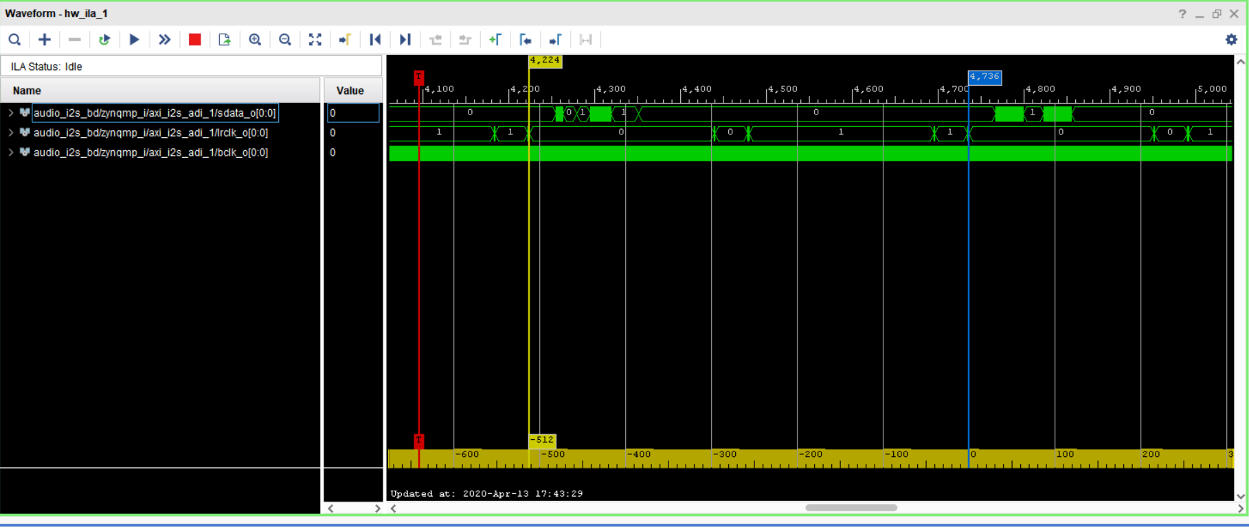
I am currently integrating the tlv320aic34 on a custom board and trying to output sound through the DAC using aplay and speaker-test.I have verified that there is serial data entering the tlv chip. I have been unsuccessful in playing back sound, but I am capable of doing a direct pass through the device. I am currectly configuring the audio codec using amixer/alsamixer and have verified that all the associated volumes are unmuted. I am trying to implement the DAC_L2 path to drive to HPLCOM and HPLOUT output ports. Here are register writes when I launch aplay (setting PCM HW parameters in the audio codec driver):

tlv reg : 9 = 48 (32-bit data word)
tlv reg : 3 = 32 
tlv reg : 101 = 1
tlv reg : 7 = 10 (Left-DAC data path plays left-channel input data, Right-DAC data path plays right-channel input data)
tlv reg : 37 = 192 (Left/Right DAC powered up, HPLOUT/HPLCOM differenetial)
tlv reg : 43 = 0 (Left DAC not muted)
tlv reg : 44 = 0 (Right DAC not muted)
tlv reg : 51 = 9 (HPLOUT not muted)
tlv reg : 58 = 9 (HPLCOM not muted)
tlv reg : 2 = 170
tlv reg : 10 = 0

I am only driving DAC_L2/R2 path, from datasheet pg 39: "can only be used if the DAC output is not being routed to multiple output drivers simultaneously" , how can I verify this? I noticed that register 94, the L/R DAC's are not indicating fully powered up. What determines the DAC to be fully powered? Any suggestions on successfully playing back soudn through any DAC path would be greatly appreciated!

Thank you in advanced

  • Hello,

    Sorry to hear you are having trouble. It looks like you are not programming register 41 which selects the output switching. In this register you can select LDAC to use DAC_L2 path by writing 0xC0. Let me know if this helps. 

    The note from pg. 39 of the data sheet can be verified by ensuring you are not routing the DAC to HPRCOM, LEFT_LOP/M, etc. This is done in registers 45-93. As for the DAC's not fullt powered up, it looks to me that you are powering them up in register 37. This is odd. Let me know if writing 0xC0 to reg. 41 helps. 

    Regards,

    Aaron

  • Hello Aaron,

    "As for the DAC's not fullt powered up, it looks to me that you are powering them up in register 37. This is odd"

    Is it odd that I am manually powering up DACs everytime I execute aplay? or Odd that the fully powered up status register is indicating low while I write to the power up register? Is it recommended to simply power on DACs at initial configuration (probing for driver)?

    I forgot to mention, I am executing these following amixer commands:

    $ # #PCM/Line PLAYBACK Volume
    $ # amixer cset numid=14 127
    numid=14,iface=MIXER,name='PCM Playback Volume'
      ; type=INTEGER,access=rw---R--,values=2,min=0,max=127,step=0
      : values=127,127
      | dBscale-min=-63.50dB,step=0.50dB,mute=0
    $ # amixer cset numid=28 118
    numid=28,iface=MIXER,name='Line DAC Playback Volume'
      ; type=INTEGER,access=rw---R--,values=2,min=0,max=118,step=0
      : values=118,118
      | dBscale-min=-59.00dB,step=0.50dB,mute=1
    $ #
    $ # #DAC PLAYBACK Volume
    $ # amixer cset numid=30 118
    numid=30,iface=MIXER,name='HP DAC Playback Volume'
      ; type=INTEGER,access=rw---R--,values=2,min=0,max=118,step=0
      : values=118,118
      | dBscale-min=-59.00dB,step=0.50dB,mute=1
    $ # amixer cset numid=32 118
    numid=32,iface=MIXER,name='HPCOM DAC Playback Volume'
      ; type=INTEGER,access=rw---R--,values=2,min=0,max=118,step=0
      : values=118,118
      | dBscale-min=-59.00dB,step=0.50dB,mute=1
    $ #
    $ # #DAC L2/R2 Path
    $ # amixer cset numid=51 2
    numid=51,iface=MIXER,name='Right DAC Mux'
      ; type=ENUMERATED,access=rw------,values=1,items=3
      ; Item #0 'DAC_R1'
      ; Item #1 'DAC_R3'
      ; Item #2 'DAC_R2'
      : values=2
    $ # amixer cset numid=49 2
    numid=49,iface=MIXER,name='Left DAC Mux'
      ; type=ENUMERATED,access=rw------,values=1,items=3
      ; Item #0 'DAC_L1'
      ; Item #1 'DAC_L3'
      ; Item #2 'DAC_L2'
      : values=2

    For the last amxier commands, my value for register 41 is 0xA0. I believe 0xC0 would be writing a reserved value? according to the datasheet I am looking at. But other than that, I still am not hearing any sound through my speaker. Any other suggestions is greatly appreciated! 

    Best regards.

  • Hello,

    Yes, it is confusing that you are reading that the L/RDAC are not fully powered up after powering them up. As for writing 0xC0, this was a typo. 0xA0 is correct. As a sanity check, are the register configurations you sent read after programming them? Perhaps a full register dump showing register contents after writing to the device will help. 

    The AIC34 also has two internal blocks. Please make sure you are applying the correct CLK signals, etc. to the write pins. Can you send over a picture of the schematic as well? What block is being used? What are the CLK frequencies?

    Regards,

    Aaron

  • Hello Aaron,

    Unfortunately, I cannot send a picture of schematic, however, I believe I am targeting the correct internal block and I have double checked the pinout to/from audio serial data bus. The clock supplied to MCLK is a free running 24.5 MHz clock and routed to the master controller and the codec, so they are synchronously and should be receiving a clock signal at all times. I have two differential output ports connected (HPLOUT,HPLCOM and MONO_LOP_A, MONO_LOM_A).

    This register dump is after all the register write configurations:

    i2cdump: WARNING! This program can confuse your I2C bus
    Continue? [y/N] y
         0  1  2  3  4  5  6  7  8  9  a  b  c  d  e  f    0123456789abcdef
    00: 00 00 aa 20 04 00 00 0a 00 30 00 01 00 00 00 20    ..? ?..?.0.?...
    10: 20 ff ff 00 78 78 00 78 78 06 00 fe 00 00 fe 00     ...xx.xx?.?..?.
    20: 00 00 00 00 20 c0 00 00 40 a0 00 00 00 2f 2f 00    .... ?..@?...//.
    30: 00 00 00 0b 2f 2f 00 00 00 00 0b 00 00 00 2f 2f    ...?//....?...//
    40: 00 03 00 00 00 2f 2f 00 02 2f 2f af 2f 2f af 0b    .?...//.?//?//??
    50: 2f 2f 00 00 00 00 0b 00 00 00 2f 2f 00 0b fe 0c    //....?...//.???
    60: 00 02 00 00 00 01 02 00 00 00 00 00 00 00 00 00    .?...??.........
    70: 00 00 00 00 00 00 00 00 00 00 00 00 00 00 00 00    ................
    80: 00 00 aa 20 04 00 00 0a 00 30 00 01 00 00 00 20    ..? ?..?.0.?...
    90: 20 ff ff 00 78 78 00 78 78 06 00 fe 00 00 fe 00     ...xx.xx?.?..?.
    a0: 00 00 00 00 20 c0 00 00 40 a0 00 00 00 2f 2f 00    .... ?..@?...//.
    b0: 00 00 00 0b 2f 2f 00 00 00 00 0b 00 00 00 2f 2f    ...?//....?...//
    c0: 00 03 00 00 00 2f 2f 00 02 2f 2f af 2f 2f af 0b    .?...//.?//?//??
    d0: 2f 2f 00 00 00 00 0b 00 00 00 2f 2f 00 0b fe 0c    //....?...//.???
    e0: 00 02 00 00 00 01 02 00 00 00 00 00 00 00 00 00    .?...??.........
    f0: 00 00 00 00 00 00 00 00 00 00 00 00 00 00 00 00    ...............

    Best regards.

  • Hello Aaron,

    Now it appears that the DACs are fully powered on, which is good. The HPLOUT is powered on too. Do I need to specify that I am driving a single ended signal? If I were to drive the DAC_R2 to HPLCOM, I would need to pass the signal through the mixer correct?

    Best regards.

  • Hello,

    No worries! You can always privately send the schematic. If you wish to do so, let me send me a friend request and you can send the schematic via direct message. If not, no worries. 

    Let me go through the configuration settings and I will also run the settings on an EVM and see if there are any issues. I will get back to you shortly. 

    Regards,

    Aaron

  • Hello Aaron,

    Yes I still am unable to, due to company policy, but I am willing to help describe more of the hardware when deemed necessary. Looking forward to your investigation and response!

    Thank you.

  • Hello,

    You would only need to specify how HPLCOM/HPRCOM is configured. This is done in registers 37/38. Can you share BCLK and WCLK frequencies as well? It looks like you are trying to achieve an Fs of 16kHz. Is this correct? If your MCLK is 24.5MHz, you are dividing by half to get a CODEC_CLK of 12.250MHz. For the AIC310x family of codecs, Fs must equal 256*Fsref. If Fsref is 48kHz, CODEC_CLK should be 12.288MHz. WCLK should also be 16kHz. 

    I would suggest enabling the PLL and setting it up using the following values:

    P = 2

    R = 3

    J = 2

    D = 6749

    Even though the Fs generation can be optimized, I would still expect to see garbage at the output and not nothing. Can you probe HPLOUT/COM and see if the DC bias is there? When the drivers are on, there is a DC bias and you have it programmed it to be 1.5V. 

    Regards,

    Aaron 

  • Hello Aaron,

    I implemented your PLL configurations, and I measured the DC bias on the HPLOUT. It is almost negligible of about ~10-20 mV. I noticed that the DC bias remains almost non existent even with the DACs powered down, so there seems to be something suppressing it. I am still in the process of measuring the wclock and bclock, will give an update soon.

    Here is the latest register dump: 

    After setting PLL:
         0  1  2  3  4  5  6  7  8  9  a  b  c  d  e  f    0123456789abcdef
    00: 00 00 aa 82 08 1a 5c 0a 00 30 00 01 00 00 00 20    ..????\?.0.?...
    10: 20 ff ff 00 78 78 00 78 78 06 00 fe 00 00 fe 00     ...xx.xx?.?..?.
    20: 00 00 00 00 20 c0 00 00 40 a0 00 00 00 2f 2f 00    .... ?..@?...//.
    30: 00 00 00 0b 2f 2f 00 00 00 00 0b 00 00 00 2f 2f    ...?//....?...//
    40: 00 03 00 00 00 2f 2f 00 02 2f 2f af 2f 2f af 0b    .?...//.?//?//??
    50: 2f 2f 00 00 00 00 0b 00 00 00 2f 2f 00 0b fe 0c    //....?...//.???
    60: 00 02 00 00 00 00 02 00 00 00 00 00 00 00 00 00    .?....?.........
    70: 00 00 00 00 00 00 00 00 00 00 00 00 00 00 00 00    ................
    80: 00 00 aa 82 08 1a 5c 0a 00 30 00 01 00 00 00 20    ..????\?.0.?...
    90: 20 ff ff 00 78 78 00 78 78 06 00 fe 00 00 fe 00     ...xx.xx?.?..?.
    a0: 00 00 00 00 20 c0 00 00 40 a0 00 00 00 2f 2f 00    .... ?..@?...//.
    b0: 00 00 00 0b 2f 2f 00 00 00 00 0b 00 00 00 2f 2f    ...?//....?...//
    c0: 00 03 00 00 00 2f 2f 00 02 2f 2f af 2f 2f af 0b    .?...//.?//?//??
    d0: 2f 2f 00 00 00 00 0b 00 00 00 2f 2f 00 0b fe 0c    //....?...//.???
    e0: 00 02 00 00 00 00 02 00 00 00 00 00 00 00 00 00    .?....?.........
    f0: 00 00 00 00 00 00 00 00 00 00 00 00 00 00 00 00    ................

    Best regards.

  • Aaron,

    Here is a logic analyzer wave capture for the bclk and wclk. I am actually not quite sure the frequency of the bclk and wclk, I will have to get back to you tomorrow. I know the i2s ip core is getting configured when launching aplay, etc. 

    Best regards.

  • Hello,

    As for measuring the DC bias on HPLOUT/COM, make sure this is being measured directly at the pin and not after an AC coupling cap. 

    I have used the same routing paths here on an EVM and verified that it should work. I do notice that there are a lot of writes to unnecessary registers. For example. 0x2f is being written to a lot of the routing registers that aren't being used. If registers aren't being used, please keep them at default configuration. 

    Looking at the picture showing the CLKs, it looks like LRCLK is not 50% duty cycle. Can  you confirm this? If using I2S, LRCLK should be at 50% duty cycle. 

    Regards,

    Aaron