This thread has been locked.

If you have a related question, please click the "Ask a related question" button in the top right corner. The newly created question will be automatically linked to this question.

TAS2770: TAS2770 Configuration for Raspberry Pi I2S

Part Number: TAS2770

Hi All, I'm trying to get a TAS2770 Amp working with a Raspberry Pi I2S Output for use as a Mono output HAT.

I've configured the Pi and I can see that PCM_BCLK (14.MHz), PCM_LRCLK(44.1kHz) and PCM_DOUT are active and getting the the amp (via a 1.8V transeiver) but I get nothing at the output. I'm using 12V for VBATT.

I can read/write registers on the TAS2770 over I2C and I've configured the registers as follows: -

  • Write 0x01 to Register 0x01 (Perform S/W reset)
  • Write 0x37 to Register 0x0A (Set sample rate to 44.1kHz, H-L FSYNC)
  • Write 0x01 to Register 0x0B (Falling edge of SBCLK)
  • Write 0x30 to Register 0x0C (Stereo Downmix)
  • Write 0x0C to Register 0x03 (Gain 17dBV (10Vpk)
  • Write 0x08 to Register 0x3C (SBCLK to DS ratio = 32, Auto Clk Config)
  • Write 00 to Regiuster 0x02 (Enable Output)

I can see I2S going into the Amp IC and I can read the detected FS_RATIO from register 0x77 but I don't see any sort of activity on the speaker output which leaves me thinking either I've missed something in the register setup or I've somehow managed to damage the device.

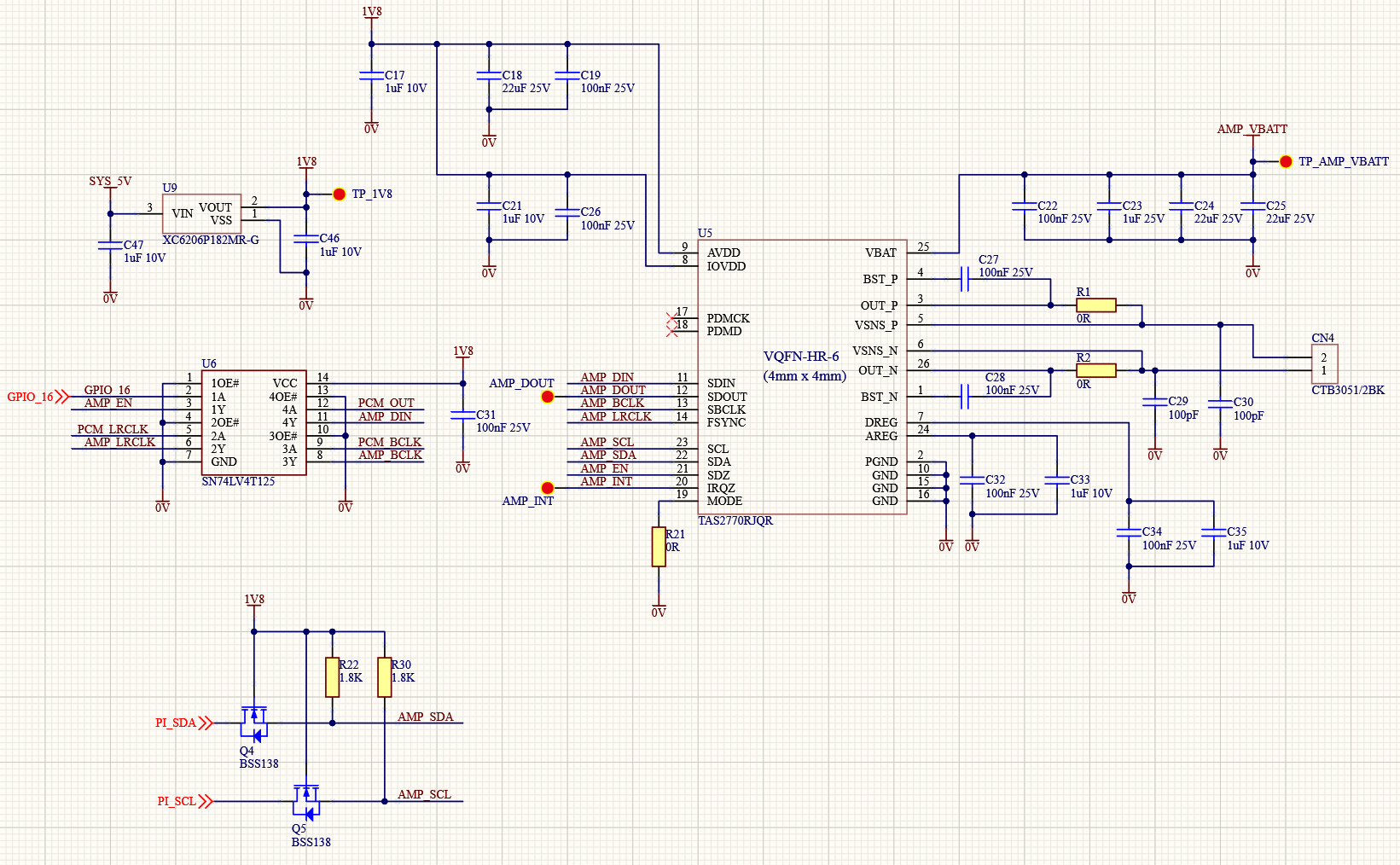
Any pointers would be much appreciated :-) Schematic below.

Cheers,

MIke.

  • Hi, Mike,

    We will take a look at this and will answer as soon as possible.

    Best regards,
    Luis Fernando Rodríguez S.

  • Hi Mike,

    Can you share your full initialization script? Or are you sending only those commands?
    You can get a initialization script using PurePath Console 3, not sure if you're using it already.

    Also please read the latched flags on registers 0x24 and 0x25, this would help to identify if there is any fault causing the device to shutdown.

    Best regards,
    -Ivan Salazar
    Applications Engineer - Low Power Audio & Actuator

  • Hi Ivan, Thanks for your quick reply on this.

    Those are the only commands I'm sending directly from the Pi. I didn't think I'd be able to generate a config script without having the eval board but if I can do that then I'll look into that too.

    I've read the registers as you suggested and get the following

    INT_LTCH0 (0x24) = 0x80 => Limiter Mute

    INT_LTCH1 (0x25) = 0x06 => VBAT UVLO, VBAT Brown Out

    Reading both those registers clears them and I see that the PWR_CTL (0x02) = 0x02 => Software Shutdown.

    So for some reason as soon as I enable the PWR_CTL = 0x00 the amp immediately shuts back down.

    I monitored the 12V going to the VBAT supply when I set the enable but I dont see any brown out or dips. Is it possible to read the Amps VBAT over I2C or can it only be done over I2S?

    Cheers,

    Mike.

  • Hi Ivan,

    Just a quick update....

    After much investigation I swapped the part on my board (no mean feat!) and initially got some noisy audio out of it! Some trial and error with the clock settings and it now sounds pretty good :-)

    Registers 0x24 & 0x25 are now reading 0x0 :-)

    I have tried to request the PureWave software via the website but I have been denied twice by the representative for some reason! I will keep trying!

    Now thatthe part isn't faulting out I can also read the on-die temperature (which I assume must be divided by 100?) and the VBAT ADC which I am dividing by 256.

    Cheers,

    Mike.