This thread has been locked.

If you have a related question, please click the "Ask a related question" button in the top right corner. The newly created question will be automatically linked to this question.

TLV320AIC3109-Q1: Microphone does not work and noise is observed

Part Number: TLV320AIC3109-Q1

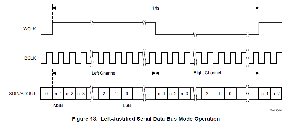
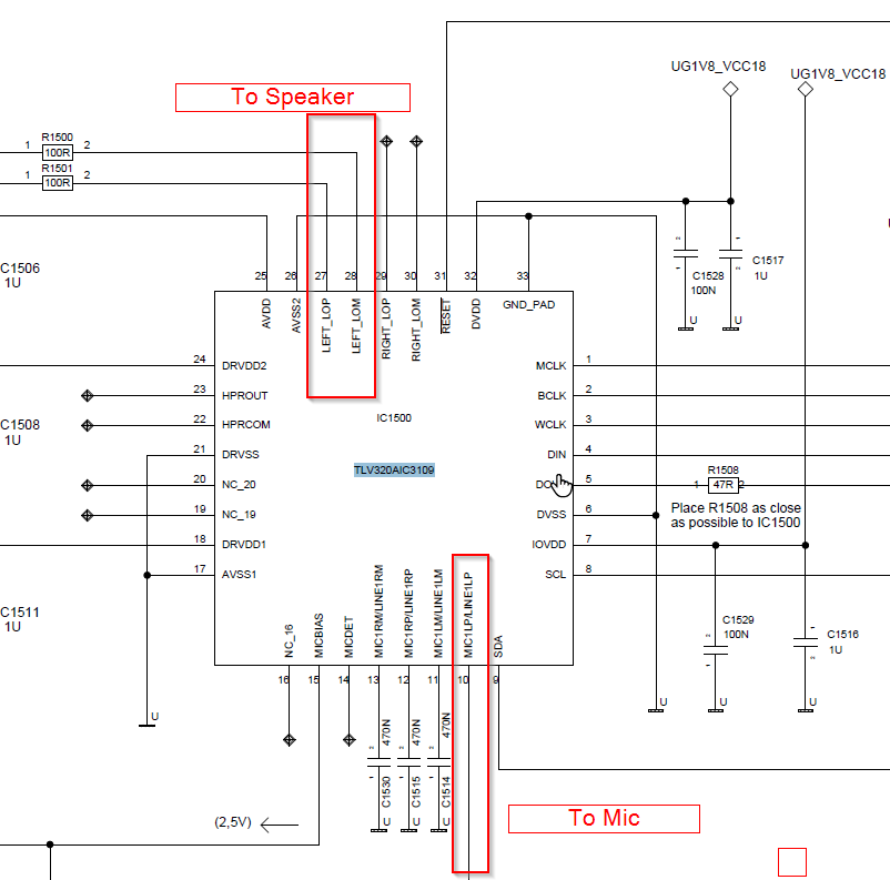
We are using the TLV320AIC3109-Q1 Codec with above mic and speaker connection. The Codec is Connected to SOC over I2S. I2S is configured in left Justified.

Sample Rate : 16000 Hz

Bit Depth : 16 bits

BitRate : 512Khz

Below are the register settings we are using .

Codec Register Description Comments C2 Verified Values
       
1( 0x01) Software Reset Register   0x00
2 (0x02) Codec Sample Rate Select Register   0x44
3 (0x03) PLL Programming Register A   0x81
4 (0x04) PLL Programming Register B   0xc0
5 (0x05) PLL Programming Register C(   0x00
6 (0x06) PLL Programming Register D(   0x00
7 (0x07) Codec Data-Path Setup Register   0x08
9 (0x09) Audio Serial Data Interface Control Register B   0xC0
10 (0x0A) Audio Serial Data Interface Control Register C   0x01
11 (0x0B) Audio Codec Overflow Flag Register   0x04
12 (0x0C) Audio Codec Digital Filter Control Register   0x54
15 (0x0E) ADC PGA Gain Control Register   0x00
16 (0x0F) Auxiliary PGA Gain Control Register   0x80 ( 0x00)
19 (0x13) MIC1P/LINE1P to ADC Control Register   0x06
21(0x15) MIC2P/LINE2P to ADC Control Register   0x78
22 (0x16)   reserved. DNP 0x78 (0x07)
24 (0x18)   reserved. DNP 0x78 (0x00)
25 (0x19) MICBIAS Control Register   0x86
37 (0x25) DAC Power and Output Driver Control Register   0x80
41 (0x29) DAC Output Switching Control Register   0x00
42 (0x2A) Output Driver Pop Reduction Register   0x16
43 (0x2B) DAC Digital Volume Control Register To be Adjusted based on measurement 0x00
82 (0x52) DAC_1 to LEFT_LOP/M Volume Control Register   0x80
86 (0x56) LEFT_LOP/M Output Level Control Register 0x0b is the value read. To be Investigated 0x09
101 (0x65) Clock Register   0x00
102 (0x66) Clock Generation Control Register   0xa2
107 (0x6B) New Programmable ADC Digital Path and I2C Bus Condition Register   0x00
109 (0x6D) DAC Quiescent Current Adjustment Register   0xc0

We are observing few issues with the above settings. 

1) The microphone does not work when the registers 22 and 24 are programmed with reserved values. The Mic works only when programmed with values for register 22 -> 0x07 , 24 -> 0x00 , 16 -> 0x00

2) When the above values are programmed we observe there microphone is having noise. (Attached the audio file for reference)

  • Hello Bharat,

    I looked through the information you provided and have a couple of questions/comments...

    1. You did not provide any CLK information. Can you please send over what frequency your clocks are running at? By the looks of your register configuration, you are using BCLK of 768kHz as an input? Please clarify.

    2. The ASI is configured for Left Justified. Can you please send over a scope shot of WCLK, BCLK and DOUT?

    3. Is the only issue with the ADC side? Are you experiencing any issues on the DAC side?

    4. It is odd that you are running into issues with the reserved registers. I ran your configuration on an EVM and did not see any issues. I was able to record a tone on the MIC1LP input using LJF in Audacity. 

    5. I see that you have the De-emphasis filter enabled. try to disable this along with the reserved registers set to their reserved vales and see if this helps?

    As for the microphone noise, this can be contributed to the Audio Serial Interface not being set up correctly or the PLL being configured incorrectly. If you are providing the right input CLK then I suspect the issue is the way the ASI is configured. 

    Regards,

    Aaron

  • Hello Aaron,

    Thanks for your reply. 

    We are using the following settings for the Codec 

    1) The bit clock rate is 512Khz and we are using the PLL to generate the clock in the codec. The clock source for the PLL is BCLK from the SoC I2S.

    3) I am observing the issue with ADC . DAC is working as I can hear the audio on the speaker when I play from SoC using aplay. 

    4) Can you the share the register settings used by you in EVM. Are there any register I am programming wrong or my calculation is wrong.

    will capture the Scope traces of the ASI and share in separate mail.

  • Hello Bharat,

    Thanks for info. The PLL is configured for the BCLK rate you are supplying. I missed a bit in my last calculation when I asked if you had a PLLCLK_IN frequency of 768kHz.

    I did notice that you are programming the device for Left Justified mode but suggesting I2S above. If you are using I2S, please leave register 9 with its default value of 0x00. In the meantime, I will gather the register settings and send them over.

    Regards,

    Aaron

  • Hello Aaron,

    We are using the I2S left justified mode and hence programmed the register 0x09 with 0xC0. I tried testing with I2S mode by programming register 0x09 with 0x00. I notice the speaker and mic does not work in this mode. Due to the lockdown situation I am not able to capture the scope trace for the I2S lines between codec and SoC. I will capture them and provide you. 

    Thank you for your support.

    Regards,

    Bharat

  • This is the Scope trace of the ASI interface. 

  • Please find the scope trace of the DOUT and BCLK and LRCK of the Codec .

  • Hello Bharat,

    Apologies for the delay in response. 

    It looks like the WCLK and BCLK edges are not sync'd correctly. The image below shows how the WCLK and BCLK edges should be synced in Left Justified. The edges of WCLK should be synced with the falling edge of BCLK.

    Regards,

    Aaron

  • Hello Aaron,

    I will check on the clock edge issue observed. Can you please provide the codec settings used for your test. I need to understand if the I2S mode and the reserved registers I mentioned earlier has any relation. As mentioned if the reserved values are programmed for the registers 21 and 24 the mic does not work. Can you please help here.

    Regards,

    Bharat

  • Hello Bharat,

    I have attached a .txt file with the register settings I used. I left the reserved registers as reserved. I was able to record data out. I also attached a picture below showing WCLK, BCLK, and DOUT. The format in the configuration is the EVM format (Write, Addr, Register, Value). The configuration should match yours except for the PLL and registers 101 and 102. 

    w 30 00 00
    w 30 01 80
    w 30 07 80
    w 30 09 c0
    w 30 0c 54
    w 30 0f 00
    w 30 13 06
    w 30 15 78
    w 30 16 78
    w 30 18 78
    w 30 19 86
    w 30 25 80
    w 30 29 00
    w 30 2a 16
    w 30 2b 00
    w 30 52 80
    w 30 56 09
    w 30 65 01
    w 30 66 00
    w 30 6d c0

    Regards,

    Aaron