Because of the holidays, TI E2E™ design support forum responses will be delayed from Dec. 25 through Jan. 2. Thank you for your patience.

This thread has been locked.

If you have a related question, please click the "Ask a related question" button in the top right corner. The newly created question will be automatically linked to this question.

TAS5720A-Q1: Issue with I2C

Part Number: TAS5720A-Q1

Hi team,

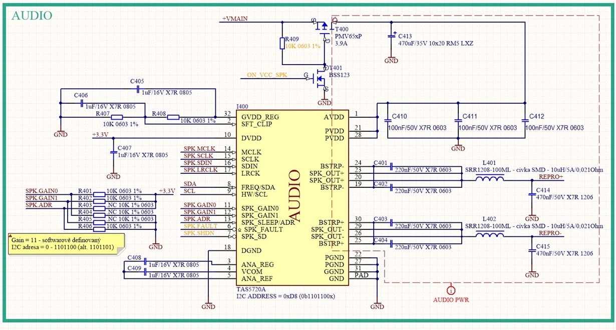
we use TAS5720A connections as datasheet recommended. Setting of I2C is kept in default values. 

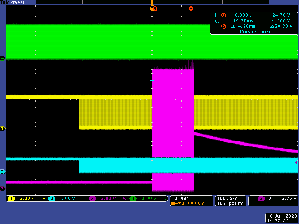
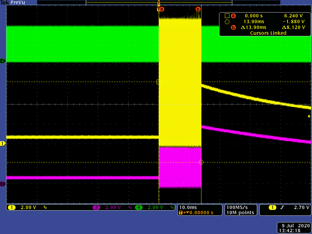
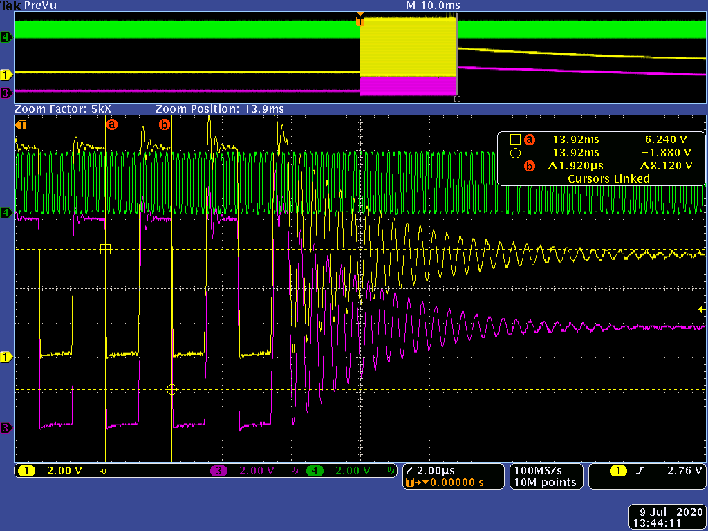
12 ms after start the amplifier turns off and i2C send error " Over Current Error Status". We don´t know, why it happen. 

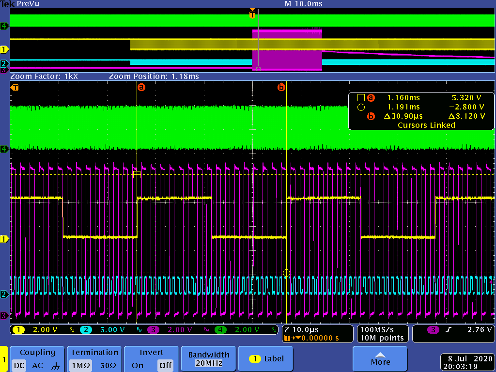
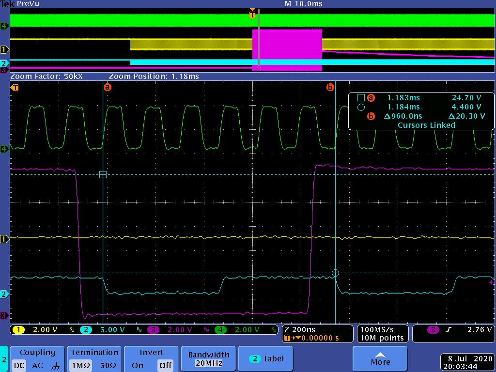
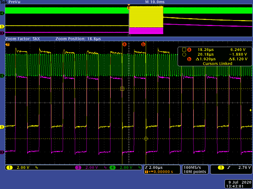
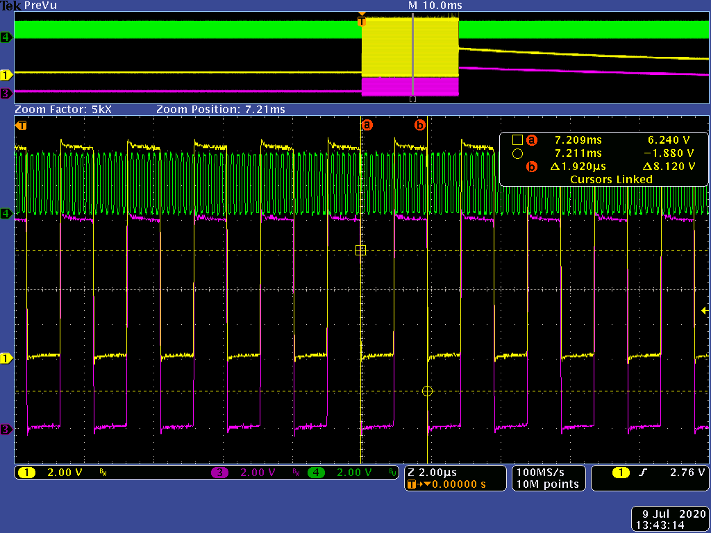
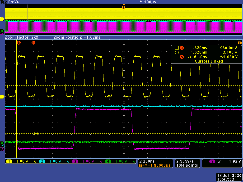
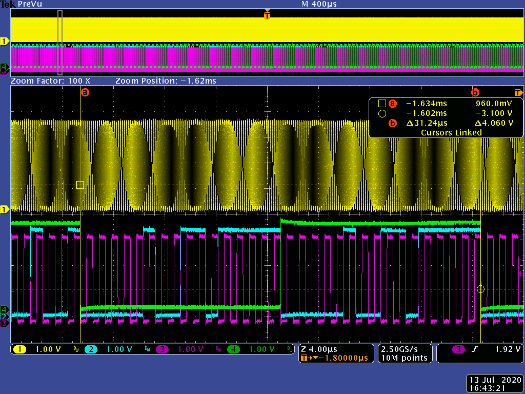
I enclose pictures (scheme and PrtScr from osciloscope) below. Green is MCLK, blue RLCLK, yellow BCLK and purple is SPK_OUT. 

Output load is 100 ohm for testing. We tried a different timing for I2S, but without any success. 

Could you help us?

Thank you.

Best Regards,

Vojta Kana

  • Hi customer,

    Can you share your I2C scripts here for our double check in EVM board? Or do you have an EVM in your hand to reproduce this issue?

    By the way, if you keep an open load, do you see similiar OC? I think PWM waveform with details before the inductor will help for further analysis.

    BR.

    Alix Wan.

  • Hi Mr. Wan,

    unfortunately, we have not EVM. I2C registers from address 0: 00 FD 14 80 CF CF 51 00 04 00 00 00 00 00 00 00 FF FC.

    Thank you,

    Regards.

    Vojta Kana

  • After start is set CLKE bit, but as soon as I2S data arrives, bit is erased and OCE bit is set then.

    Also we cannot found information about limit fSPK_AMP, there is just recommended value 384 kHz. 

    Thank you for help.

    Best regards,

    Vojta Kana

  • Hi Kana,

    With your configurations of the registers, i try to reproduce this issue in EVM board. But it turns out that it works well in my board.

    From the scope, is it possible that device is configured as PBTL? I understand the register value is BTL but just in case, can you read it back for double check?

    In addition, can you open the load for test? Is it possible output is short to GND, PVDD or each other?

    BR.

    Alix Wan.

  • Hi Wan,

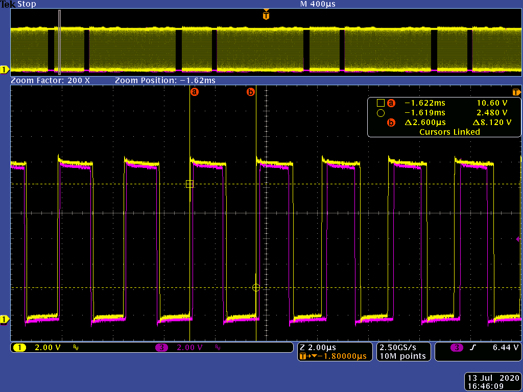
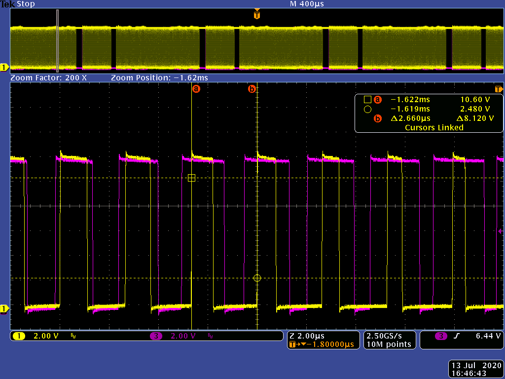
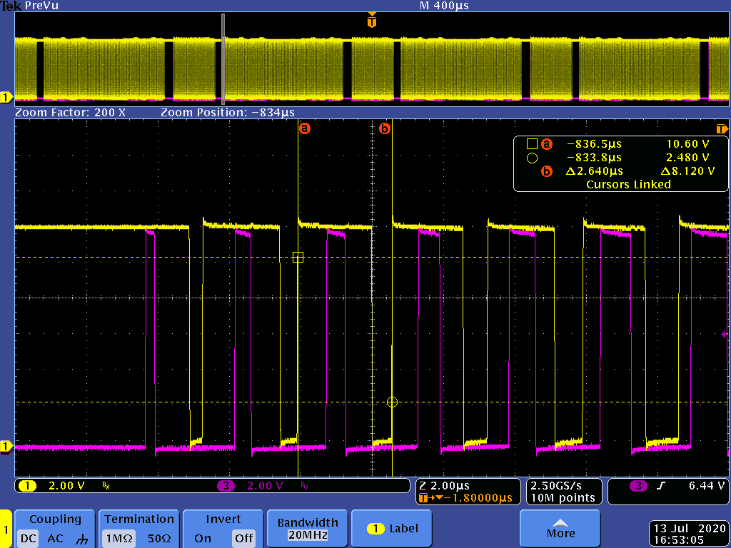
    we switched IC TAS5720A to PBTL mode. Also we tried different settings of I2C registers. Nevertheless, output before inductor do not behave as PBTL.

    Starting sequence: 

    1. +3.3 V occurring
    2. +12 V 
    3. MCLK
    4. I2S data
    5. Setting TAS5720A via I2C
    6. Enable pin SHDN = 1

    I2S registers:

    00 FD 03 80 CF CF B1 00 00 00 00 00 00 00 00 00 FF FC

    Changes again Default values:

    DigBoost                             00:         +0 dB

    SerialAudioInFormat         011:         16Bits, Right Justified

    PWM rate sel                    011:         12*LRCK

    PBTL enable                         1:         enable


    I2S:

    MCLK = 6 144 375 Hz

    BCLK = 2 048 000 Hz

    LRCLK = 32 000 Hz

    fSPK_AMP = 384615 Hz

    I also attached some scope pictures.

    I2S MCLK

    SPK_OUT

    SPK_OUT2

    SPK_OUT3

    SPK_OUT4

    ValueOnI2S_0x9BE

    Do you know, what can be wrong?

    Thank you.

    Best regards.

    Vojtech Kana

  • Hello Customer,

    Sorry for the delay. 

    From your read out register values, it is checked to be ok. 

    Can you try to configure 0x06 to switch between BTL and PBTL to check whether it is I2C configuration that makes this issue.

    Or can you help to try hardware mode? Just to eliminate the possible hardware connection error.

    BR

    Alix Wan