This thread has been locked.

If you have a related question, please click the "Ask a related question" button in the top right corner. The newly created question will be automatically linked to this question.

TAS2770: Connection recommendations to TAS2770 and microcontroller (Teensy)

Part Number: TAS2770

Hi,

I'm hoping to use a Teensy 4.1 to drive a TAS2770 digital input mono class-D audio amplifier (https://www.ti.com/product/TAS2770#tech-docs), but am not sure how the I2S pins on the Teensy align. I'm particularly wondering how to read the TDM serial data output from the TAS2770. 

On the TAS2770 I will need:

SDIN (TDM serial data input)
SDOUT (TDM serial data output)
FSYNC (word select)
SBCLK (TDM serial bit clock)

Some questions:

1) is FSYNC the same as LRCLK? I'm new to audio/I2S so am not sure if there's a naming convention scheme that makes these pinouts self-explanatory. 

2) How would I read the SDOUT pin? My understanding is that the audio input pins to the Teensy are for audio signals (to ADC), rather than serial. 

3) Does the TAS2770 EVM have 3.3v - 1.8v level shifters for I2C and I2S as needed to drive the TAS2770? 

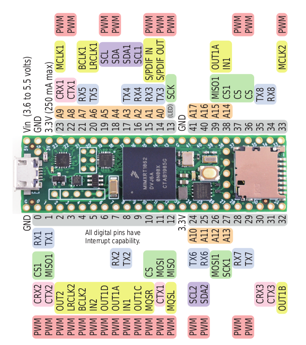
Just for reference, here's a picture of the microcontroller pinout I'm using (yellow pins are for audio). 
Thank you very much,

Chris

  • Hello Chris,

    Welcome to E2E and thank you for your interest in TAS2770. 

    To answer some of your questions:

    1. Yes, you are correct that FSYNC is the same as the LRCLK (Left-Right Clock)

    2. SDOUT pin on TAS2770 follows the I2S/TDM format. To enable SDOUT transmit, configure the output slot. Also, SDOUT is coming back in packsts of 16/24/32 bits (the same way it does for SDIN) (Reference to datasheet about SDOUT)

    3. I2C bus lines can be pulled to IOVDD with a resistor for logic high. We recommend external pull-up resistors to be 2k - 4.7k ohms (Reference to I2C section of the datasheet)

    Let me know if you have any more questions.

    Regards,

    Jin Gao

  • Thanks Jin. 

    Is the SDOUT pin definitely needed to read the IV sense? Or can the IV sense registers be read over I2C? 

    I also want to clarify: is the purpose of the SDOUT pin for daisy chaining devices to get multichannel audio? Or is it being used in the TAS2770 for IV sense feedback? I'm wondering if I can leave it disconnected, and still achieve full functionality, assuming I'm not daisy chaining multiple devices.

    Thanks,

    Chris 

  • Hello Chris,

    No problem. 

    You are correct. the SDOUT can be used to read IV Sense, VBAT, and etc. You can assign them to a specific slots and read via TDM if you want to read multiple data. I don't believe you can read registers for IV sense data.

    The purpose of SDOUT is to read the above mention data streams or to use it to chain multiple channels. If you are just using one device and do not plan to read from SDOUT, you can leave it disconnected. The functionality of IV sense will not be impacted by SDOUT, as long as you enable IV sense. Also, if you mind me asking, what general application is the device used for?

    I hope this clears your concerns. Let me know if you need anything else.

    Regards,

    Jin Gao

  • Hi Jin,

    I'm using this to drive an actuator coil for a robotics application. 

    I've been struggling to interface with the TAS2770 EVM with an external microcontroller over I2C (I was able to play audio successfully over PPC3, but need an external microcontroller for my application).

    On my EVM, I have the following jumper settings:

    • J2 - connected
    • J6 - connected
    • J11 - all open 
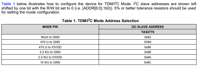
    • J13 - I2C address set to 0x82
    • J21, J22, J18 - connected
    • J12 - connected 

    I have a very simple Arduino sketch that tests communication on a bunch of I2C addresses, and reports back on the addresses that it was able to reach successfully. 

    Here's the relevant code snippet: 

    Wire.begin();
    Wire.setClock(100000);
      
    for(int address=0x00; address < 0x8e; address++){
      
        Wire.beginTransmission(address);
        error = Wire.endTransmission();
      
        if (error == 0) {
          Serial.print(F("Device found at address 0x"));
          if (address < 16) {
            Serial.print("0");
          }
          Serial.println(address,HEX);
        } 
        delay(50);           
      }

    However, I only see I2C addresses 0x41 and 0x42 appear, regardless of J13's settings (the addresses disappear if I disconnect J6 or J12 I2C-SEL). I'm confused why 0x41 and 0x42 appear, rather than 0x82. I've verified that my SCL and SDA I2C signals are being transmitted correctly from my microcontroller with an oscilloscope. Any explanation for this? 

    What steps need to be taken in order to communicate over a microcontroller I2C to the TAS2770 EVM? 

    Thanks,

    Chris

  • Hello Chris,

    That is a great question. Have you tried addressing 0x41 and 0x42? Did that work for you? I2C address 0x41 and 0x82 are in fact equivalent. 0x41 is the 7 bit I2C address, the datasheet just left shifted by one bit for the R/W bit. Also, you may need to restart the board when there is an I2C address change for the device to adjust during power-up.

    External I2C control is specified in TAS2770 EVM User's Guide. Your setup looks fine to me, but you can verify it for quick reference. One thing to note is that make sure J1 is set to the voltage level of your external device's logic level.

    In addition, following up to a related thread from you. TAS2770 has a default High Pass Filter built in, you might want to consider bypass that if you want to test the  DC output to your actuator. 

    Let me know if you need anything else.

    Regards,

    Jin Gao

  • Hello Chris,

    I hope you were able to resolve your issue. Due to thread inactivity, I will have to close this thread soon. However, please feel free to post your questions or comments in case of additional observations.

    Thank you for using E2E,

    Jin Gao

  • Hi Jin,

    Yes, I was. Thanks for the help on this! Feel free to close the thread :)

    Chris