

Hello,
We have a TAS2770 audio amplifier connected to the I2s output of a Nordic Nrf52832 µC.
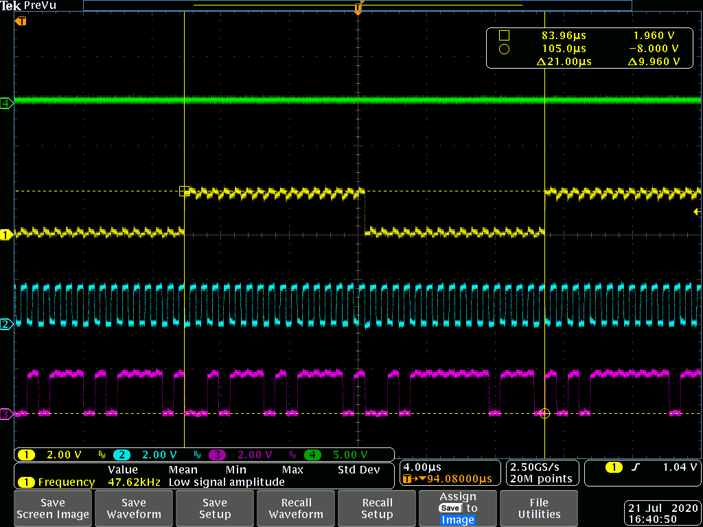
But nothing on loudspeaker output (in green on the attached scope screen)
I've configured the Nrf52 and can see I2S signal (yellow for FSYNC, blue for LBCLK, and purple for SDIN).
I write TAS2770 registers:
I2C0_WriteReg(TAS2770_ADDRESS, TAS2770_BOOKCTL_PAGE, 0); // Page 0
I2C0_WriteReg(TAS2770_ADDRESS, TAS2770_BOOKCTL_REG, 0); // book 0
I2C0_WriteReg(TAS2770_ADDRESS, TAS2770_SW_RST, 1); // software reset
nrf_delay_ms(1);
I2C0_WriteReg(TAS2770_ADDRESS, TAS2770_TDM_CFG_REG0, 0x06); // 48KHz, Auto TDM off, Frame start Low to High
I2C0_WriteReg(TAS2770_ADDRESS, TAS2770_TDM_CFG_REG1, 0x02); // Offset = 1, Sync on SBCLK rising edge
I2C0_WriteReg(TAS2770_ADDRESS, TAS2770_TDM_CFG_REG2, 0x30); // TDM stereo, Word = 16 bit, Frame = 16 bit
I2C0_WriteReg(TAS2770_ADDRESS, TAS2770_TDM_CFG_REG3, 0x10); // Right Ch = TDM slot 1, Left Ch = TDM slot 0
I2C0_WriteReg(TAS2770_ADDRESS, TAS2770_PLAY_CFG_REG0, 0x01); // 11.5 dB gain 5.32Vpk
I2C0_WriteReg(TAS2770_ADDRESS, TAS2770_CLK_CGF, 0x08); // sblk to fs ratio = 32
I2C0_WriteReg(TAS2770_ADDRESS, TAS2770_PWR_CTRL, 0); // power up audio playback with I,V enabled
Is there a bad confuguration?
Here is the reading of the TAS 2770 registers.
TAS2770 reg 0x0 = 0x0
TAS2770 reg 0x1 = 0x0
TAS2770 reg 0x2 = 0x0
TAS2770 reg 0x3 = 0x0
TAS2770 reg 0x4 = 0x0
TAS2770 reg 0x5 = 0x0
TAS2770 reg 0x6 = 0x0
TAS2770 reg 0x7 = 0x6
TAS2770 reg 0x8 = 0x0
TAS2770 reg 0x9 = 0x8
TAS2770 reg 0xa = 0x6
TAS2770 reg 0xb = 0x2
TAS2770 reg 0xc = 0x30
TAS2770 reg 0xd = 0x10
TAS2770 reg 0xe = 0x0
TAS2770 reg 0xf = 0x2
TAS2770 reg 0x10 = 0x0
TAS2770 reg 0x11 = 0x4
TAS2770 reg 0x12 = 0x6
TAS2770 reg 0x13 = 0x7
TAS2770 reg 0x14 = 0x8
TAS2770 reg 0x15 = 0x14
TAS2770 reg 0x16 = 0x76
TAS2770 reg 0x17 = 0x10
TAS2770 reg 0x18 = 0x6e
TAS2770 reg 0x19 = 0x1e
TAS2770 reg 0x1a = 0x58
TAS2770 reg 0x1b = 0x1
TAS2770 reg 0x1c = 0x14
TAS2770 reg 0x1d = 0x4e
TAS2770 reg 0x1e = 0x0
TAS2770 reg 0x1f = 0x0
TAS2770 reg 0x20 = 0xfc
TAS2770 reg 0x21 = 0xb1
TAS2770 reg 0x22 = 0x0
TAS2770 reg 0x23 = 0x0
TAS2770 reg 0x24 = 0x0
TAS2770 reg 0x25 = 0x0
TAS2770 reg 0x26 = 0x40
TAS2770 reg 0x27 = 0x8d
TAS2770 reg 0x28 = 0x50
TAS2770 reg 0x29 = 0x79
TAS2770 reg 0x2a = 0x30
TAS2770 reg 0x2b = 0xa1
TAS2770 reg 0x2c = 0x0
TAS2770 reg 0x2d = 0xa4
TAS2770 reg 0x2e = 0x80
TAS2770 reg 0x2f = 0x2
TAS2770 reg 0x30 = 0x5
TAS2770 reg 0x31 = 0x0
TAS2770 reg 0x32 = 0x81
TAS2770 reg 0x33 = 0x0
TAS2770 reg 0x34 = 0x0
TAS2770 reg 0x35 = 0x0
TAS2770 reg 0x36 = 0x0
TAS2770 reg 0x37 = 0x0
TAS2770 reg 0x38 = 0x0
TAS2770 reg 0x39 = 0x0
TAS2770 reg 0x3a = 0x0
TAS2770 reg 0x3b = 0x0
TAS2770 reg 0x3c = 0x8
TAS2770 reg 0x77 = 0x17
TAS2770 reg 0x7d = 0x10
TAS2770 reg 0x7e = 0xdc
The register 0x77 is read at 0x17, so FS_RATE_V = error condition. Why do I have this fault? How is it triggered?
Thanks for your help.
Eric
