Part Number: PCM2912A
Hi
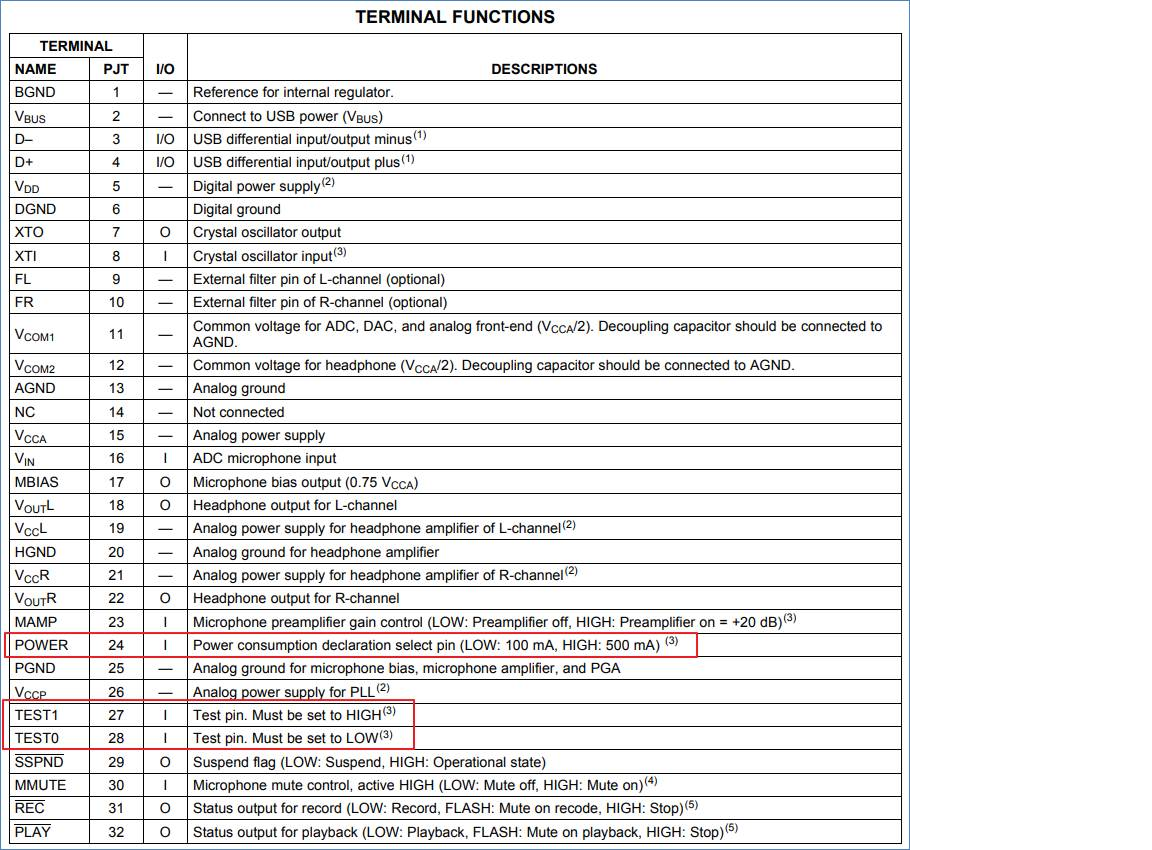
1. Set the power consumption of the POWER pin to 100mA or 500mA >>> In what situation is it applied?
2. TEST 0, 1 >>> Does the resistance test point need to be reserved?In what application situation is the measurement performed?