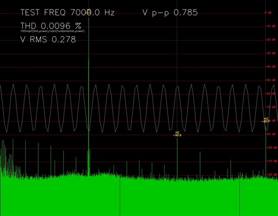
In the PCM2704 data sheet, distortion figures at different load resistances (impedances?) are given - distortion is higher at lower impedance.
In the supplied reference designs, something resembling a 'Zobel network' to ground is shown at the output, regardless of whether the DAC is driving headphones directly or an amplifier. A DC resistance to ground is also shown, varying from 330R in one example, to 3k3 in others. I don't seem to be able to find any reference to these components elsewhere in the data sheet.
What is the significance of these components? Are they required for stability, high frequency noise filtering, and/or tailoring of the frequency response? Is a DC path to ground essential? When should one use a 330R resistance, and when 3k3? Do the specified distortion figures assume the inclusion of these components?
Many thanks in advance for any help anyone can give me on this.


