Because of the Thanksgiving holiday in the U.S., TI E2E™ design support forum responses may be delayed from November 25 through December 2. Thank you for your patience.

This thread has been locked.

If you have a related question, please click the "Ask a related question" button in the top right corner. The newly created question will be automatically linked to this question.

TAS5715: The Possibilities of different AMP output level

Part Number: TAS5715

Dear TI team,

Thanks for taking time to read my post.

We designed a speaker with TAS5715 PHPR chip and followed the guidance of user manual.

But we find the output level of each board are different, some higher and some lower than it should be.

Would you please help me find out the possibilities may cause the differences?

The output sample rate we're using is 384KHz

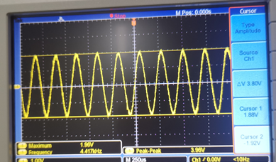
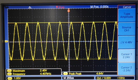
And there are two pictures for reference, which is the test result from different board. 

The test condition is 4.4K sine wave

Any questions, please feel free to let me know.

Result one, lower than it should be:

Result Two, it's normal:

Best regards,

Joanna

  • Hello Joanna,

    Can you upload your picture again as i cannot see them? Thanks!

    BR,

    Alix Wan.

  • Hello Alix

    Please kindly check the attachment.

    Output sample rate:384KHz

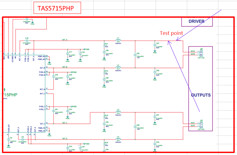
    Schematic diagram

    Result one, lower than it should be:

    Result two, it's normal:

    Best regards,

    Joanna

  • Hi Joanna,

    Do you find the issue among different PCB boards with the same hardware design and I2C configurations?

    If yes, may you confirm:

    1. Can this issue be stably repeated in abnormal boards? What is the failure rate for among all your boards?
    2. To make sure hardware design and I2C configurations are the same between normal board and abnormal boards?
    3. To check the gain setting and do a comparison between abnormal boards and abnormal boards:
      1. PVDD voltage;
      2. To check:
        1. in small input level, will the output level the same?
        2. In the maximum input level (0dB), will the output level the same?
      3. See page 5 of the datasheet to check: DRC settings, volume settings by reading back the values from abnormal boards.

    With the experiments above, it can help us to see whether which part (PVDD, volume, DRC) that leads to this issue. Thanks!

    BR,

    Alix Wan