Part Number: OPA1637
Other Parts Discussed in Thread: TPA3251
Trying to make sure I understand the extant work on this application (section 9.2.1.1 in the OPA1637) as part of some article work for AX.
I see now the stated DAC output current is in fact 3.5mA common mode with +/-2mA around that on each side (just have to read close) - that makes perfect sense and the -3.5V into the CM control sets the FDA output at -3.5V level shifitng up to 0V at the DAC output, few small things I can't help notice in this section shown here -
1. The 1kmho should be 1kohm
2. Odd to call this a Butterworth filter stage. Normally folks imply they are providing complex pole pairs with those poles lying on a circle of equal w0 radius in the negative s-plane (a 2nd order Butterworth, those poles are at 45deg). This ckt is just two real poles (no peaking you would expect), not actually a Butterworth in the strict filtering nomenclature.

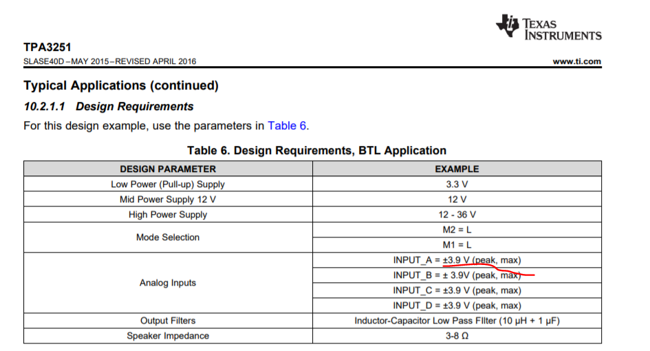
And then moving to the output side, that TPA3251 (quite the part!!) quotes 7kohm differential input R. Using 1uF coupling caps puts that HP pole at 45Hz. I would have expected lower, and the examples in the TPA3251 show a 10uF coupling cap to get 4.5Hz HP. This interface of course attenuates the output noise from the amplifier below 10Hz, don't really need to consider the 1/f noise effects for most solutions in that case.
The TPA3251 reports a maximum allowed input Vpp of 7.9Vpp, the example design in the OPA1637 seems to be producing 8Vpp maximum at the output pins attenuated to 7.91Vpp with those 75ohm to 7.5kohm nominal input R? That seems a little close, especially if you imagine (not specified) tolerancing on that 7.5kohm.