Hi TI,
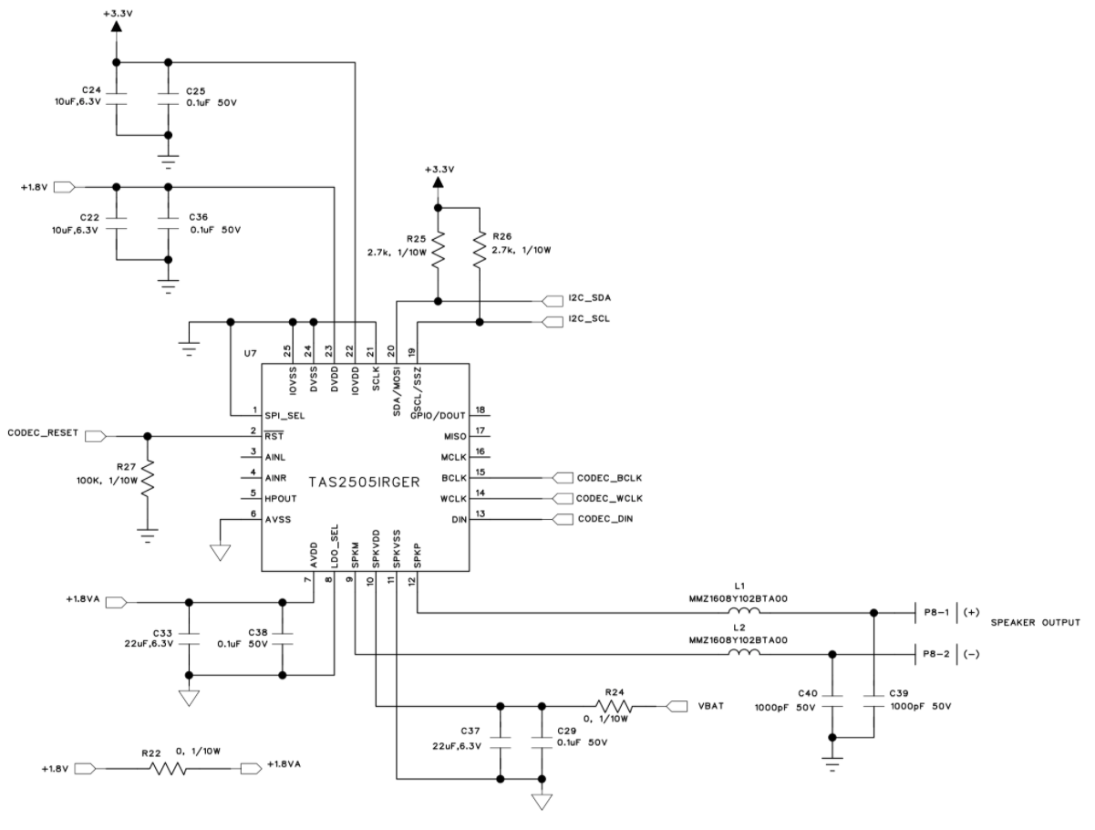
I am using the TAS2505 as an amp and speaker driver which is fed with an I2S signal. The input is a sine wave (800Hz), which I have confirmed with a logic analyser is being sent properly over I2S (16kHz sample rate, 16-bit 2's complement, MSB first, and the first bit of each sample is sent on the *second* rising BCLK edge after a WCLK transition just like in the timing diagram here https://en.wikipedia.org/wiki/I%C2%B2S). The output is a 4Ω 2W speaker and HP output is disabled (N/C).
When I play the audio, it sounds very noisy and scratchy. I am trying to clean up the audio so the playback is clear and crisp.
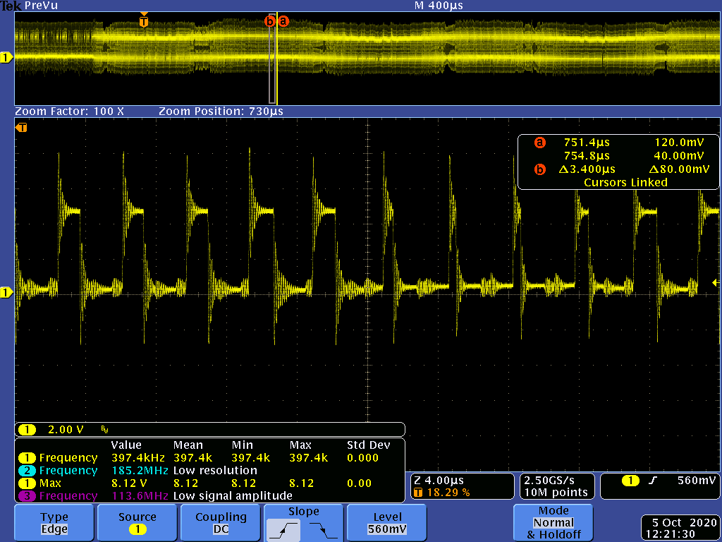
I was expecting to see the same sine wave on the speaker pin outputs with an oscilloscope, but instead I see a square wave of sorts with what appears to be ringing at each level. I get a similar signal if I use a sawtooth wave over I2S. I'm somewhat new to audio processing, so I could be interpreting it incorrectly. Is this an expected signal, or indicative of a failure?
My register settings are as follows:
enum page0_registers {
    PAGE_SEL = 0x00,
    P0_SW_RESET = 0x01,
    P0_CLOCK_CTRL1 = 0x04,
    P0_CLOCK_CTRL2 = 0x05,
    P0_CLOCK_CTRL3 = 0x06,
    P0_CLOCK_CTRL4 = 0x07,
    P0_CLOCK_CTRL5 = 0x08,
    P0_CLOCK_CTRL6 = 0x0b,
    P0_CLOCK_CTRL7 = 0x0c,
    P0_DAC_DOSR_MSB = 0x0d,
    P0_DAC_DOSR_LSB = 0x0e,
    P0_CLOCK_CTRL10 = 0x19,
    P0_CODEC_IFACE_CTRL1 = 0x1b,
    P0_CODEC_IFACE_CTRL2 = 0x1c,
    P0_MISO_CTRL = 0x37,
    P0_SCLK_CTRL = 0x38,
    P0_DAC_PROC_BLK = 0x3c,
    P0_DAC_CHAN_CTRL1 = 0x3f,
    P0_DAC_CHAN_CTRL2 = 0x40,
    P0_DAC_VOL_CTRL = 0x41,
};

enum page1_registers {
    //0: page control
    P1_REF_CTRL = 0x01,
    P1_LDO_CTRL = 0x02,
    P1_PLAY_CTRL = 0x03,
    P1_COMMON_CTRL = 0x0a,
    P1_SPK_AMP_VOL_CTRL1 = 0x2d,
    P1_SPK_VOL_CTRL1 = 0x2e,
    P1_SPK_AMP_VOL_CTRL2 = 0x30,
    P1_RESERVED_52 = 0x52,
};

// Playback settings for the Class-D amp
// Page switch to Page 0
WREG(PAGE_SEL, 0x00);
// Assert Software reset
WREG(P0_SW_RESET, 0x01);

// Page Switch to Page 1
WREG(PAGE_SEL, 0x01);
// LDO output programmed as 1.8V and Level shifters powered up.
WREG(P1_LDO_CTRL, 0x00);

// Page switch to Page 0
WREG(PAGE_SEL, 0x00);
// DAC Instruction programming PRB #1
WREG(P0_DAC_PROC_BLK, 0x01);
// CODEC_CLKIN=PLL. PLL=BCLK
WREG(P0_CLOCK_CTRL1, 0x07);
// PLL ON: P=1, R=4
WREG(P0_CLOCK_CTRL2, 0x94);
WREG(P0_CLOCK_CTRL3, 0x27); //PLL J value
WREG(P0_CLOCK_CTRL4, 0x00); //PLL D MSB value
WREG(P0_CLOCK_CTRL5, 0x00); //PLL D LSB value
// CDIV_CLKIN=BCLK
WREG(P0_CLOCK_CTRL10, 0x01);
vTaskDelay(pdMS_TO_TICKS(10)); //delay 10ms for PLL to stabilise (app ref s3.2.3)
// Codec Interface control Word length = 16bits. BCLK&WCLK inputs. I2S mode.
WREG(P0_CODEC_IFACE_CTRL1, 0x00);
// Data slot offset 00
WREG(P0_CODEC_IFACE_CTRL2, 0x00);
// DAC NDAC Powered up, NDAC=1
WREG(P0_CLOCK_CTRL6, 0x81);
// DAC MDAC Powered up, MDAC=2
WREG(P0_CLOCK_CTRL7, 0x82);
// DAC OSR(9:0)-> DOSR=16
WREG(P0_DAC_DOSR_MSB, 0x00);
WREG(P0_DAC_DOSR_LSB, 0x10);
// Disable MISO pin
WREG(P0_MISO_CTRL, 0x00);
// Disable SCLK pin
WREG(P0_SCLK_CTRL, 0x00);
// Only LDAC powered up. Dac path setup LDAC data Mono of LDAC and RDAC. RDAC data disabled. Soft step 1 per Fs.
WREG(P0_DAC_CHAN_CTRL1, 0xb0);
// DAC volume for Left channel not muted. Right DAC muted.
WREG(P0_DAC_CHAN_CTRL2, 0x04);
// LDAC digital gain 0dB
WREG(P0_DAC_VOL_CTRL, 0x00);

// Page Switch to Page 1
WREG(PAGE_SEL, 0x01);
// Master Reference Powered off
WREG(P1_REF_CTRL, 0x00);
// Output common mode for DAC set to 0.9V (default)
WREG(P1_COMMON_CTRL, 0x00);
// LDAC AFIR is 6th order FIR filter and Powered up.
WREG(P1_PLAY_CTRL, 0x00);
// SPKL attn. Gain=0dB
WREG(P1_SPK_VOL_CTRL1, 0x00);
// SPKL driver PGA Gain=6.0dB
WREG(P1_SPK_AMP_VOL_CTRL2, 0x10);
// SPK OSCP enabled, OCP Degltich=4, OTP enabled, OTP Deglitch=5
WREG(P1_RESERVED_52, 0x00);
// SPK powered up
WREG(P1_SPK_AMP_VOL_CTRL1, 0x02);
Are these register settings correct for the input I2S data that I am supplying?
Thanks in advance, any help will be appreciated.
Matt.


