Part Number: TAS5720L
Hi,
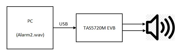
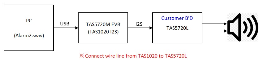
Our customer is using TAS5720L device.
The issue is that output p/n is common not differential.
Could you please check and guide?
* Register setting
[0x00]Audio Device ID = 0x01
[0x01]Audio Power Control = 0xFD
[0x02]Audio Digital Control1 = 0x04
[0x03]Audio Digital Control2 = 0x80
[0x04]Audio Volume Control = 0xAF
[0x06]Audio Analog Control = 0x55
[0x08]Audio Status = 0x08
[0x10]Audio Digital Clipper2 = 0xFF
[0x11]Audio Digital Clipper1 = 0xFC
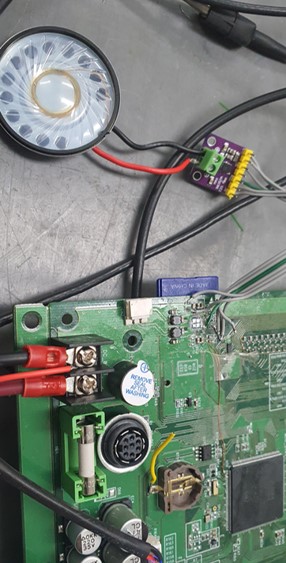
* Schematic

* Output waveform at 1, 2 of CN2

Best Regards,
Michael