This thread has been locked.

If you have a related question, please click the "Ask a related question" button in the top right corner. The newly created question will be automatically linked to this question.

OPA1652: Constant current sink design...opamp pulls down 5v dac on inverting input to 1v. Is my feedback configuration viable?

Part Number: OPA1652

Hi All,

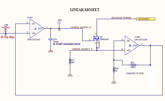
I have this constant current sink which im using to provide a controled current 0-200mA but im having a few issues with it. i did have a 1kohm pulldown on the output but it caused the opamps to get quite hot so i removed it. The issue im having is that the output of the dac is being pulled down to 1v when it is connected to the input of the op amp. my question is...can i connect the output of the second opamp to the input of the first to give my negative feedback, like this below or have i caused some kind of latchup condition on the op amp?

Many thanks

Liam 

  • Hi Liam,

    What supply voltages are you applying to the OPA1652 supply pins, and the using to power the solenoid? This circuit may have stability problems due to the design. The OPA1652 is very likely to become unstable with a 100 nF capacitor, and the MOSFET input capacitance load seen at its output. Also, there the phase shift contributed by the U14B amplifier. If the op amps are getting hot, then they may be dissipating high power due to an unexpected oscillation. Use a DSO and 10x probe to observe the U14A and U14B inputs and outputs.

    Regards, Thomas

    Precision Amplifiers Applications Engineering

  • Hi Thomas,

    thanks for getting back to me. The supply is +-15v. I have removed the 100nF cap from the output of the first opamp and it doesnt seem to have made much difference. The opamps arent getting hot any more after i removed a 1k pull down resistor from the output of opamp b(this isnt shown on the diagram because i already removed it so i took it off the schematic.i measured the inputs and outputs with a 10x oscilloscope and found the following.

    out A: 15V

    -A: 0V

    +A: 1V (it is set with a microcontroller to ramp from 0-5v every 5 seconds then reset to 0.)

    Out B: 0V

    -B: 0V

    -A: 0V

    all are stable with no oscillation.

    this is without any voltage applied to the Mosfet drain so it is what i would expect. What im wondering though is why wouldnt my DAC be able to go past 1V? i think next i will try to remove the feedback from opamp B to A and see if that allows the DAC to get to 5V. If you have any other ideas ill try them too.

    Many thanks

    Liam

  • Hi Liam,

    The OPA1652 input following the DAC should not load its output. It has an extremely high input impedance. What is the DAC part number that you are using in the circuit? Is it truly a voltage output DAC?

    Regards, Thomas

    Precision Amplifiers Applications Engineering

  • Hi Thomas,

    Yes this was what was making me think the op amp is damaged or in latchup. the DAC im using is a MAX5216. i have tried it with the outpit disconnected from the opamp input and i can see the output go from 0-5v as i would expect. its only with the opamp reconnected that i see the voltage being capped at 1v. Another thing that makes me think its a latchup it that the sawtooth patern is still the same below 1v and it sudenly stops being able to go any higher when it reaches around 0.9v

    here is the link to the datasheet for the DAC...

    Many thanks

    Liam

  • Hi Liam,

    Thank you for providing the DAC information. I don't find any reason why it should have an issue directly driving the OPA1652 input in a properly functioning circuit. 

    Our op amp products are fully analyzed and then tested for latch-up behavior during their product development phase. They have to pass all latch testing in order to be released to market, and that includes the OPA1652. I wouldn't expect it to latch as a response to an applied input voltage well within its common-mode input range.

    The results you are having strongly suggest the OPA1652 device you are testing has a damaged non-inverting input. If it is damaged it may have a diode junction whose forward voltage must be overcome for the path to turn on and present a low resistance load to the DAC. That might explain why the input can only be driven to about 0.9 V before its loads the DAC output down.

    Do you have another OPA1652 or other high performance op amp you try in place of the current op amp? That should be a quick way to determine if the current op amp is the problem.

    Regards, Thomas

    Precision Amplifiers Applications Engineering

  • Hi Thomas,

    Thanks again for the help. Yesterday i removed the feedback from opamp B to the inverting input of opamp A and the DAC was able to reach 5v so im now sure that it is the feedback between the opamps that is causing the issue. The board i am testing on has 3 identical circuits and they all behave the same way, but it is possible that they were all damaged when the 1k resistor was on the output and the opamps were overheating. I have another board which I haven't powered up yet, I have removed the resistors that were causing the overheating on the second board so I can retest and see if it will still have an issue with the feedback. One way or another i am sure you are right that the op amp is broken because even if the non inverting input has a lower voltage than the inverting input the output stays high at +15v. The only thing i'm not sure about is if the feedback caused the opamps to be damaged or if it was resistor on the output or if there is something else i'm missing

    Many thanks

    Liam

  • Hi Thomas,

    So today i tried my other board...i removed the cap from the output of opamp a and the resistor from the output of opamp b . I also removed the feedback from 2 out of the three instances of the circuit on this new board. I then powered and programmed the controller. I set all three DACs to output 5v and only the 2 with no feedback were able to go past 0.9v. the opamps didnt heat up this time so all i can conclude is that the feedback configuration between the 2 opamps on chip cannot be done, unless you have any other possibilities?

    Many thanks

    Liam

  • Hi Liam,

    The OPA1652 op amps in your application circuit do not have any significant resistive loads on the output so they shouldn't be consuming much current beyond the quiescent current. They only draw about 2 mA and shouldn't be getting hot to the touch. When you observe them getting hot it could be an indicator that they are in oscillation. In such case, their output may be switching at a high frequency and the op amp is drawing much more current through the output stage than normal. You can observe the output of U1 and U2 with a DSO and 10x probe and check for a high frequency oscillation. Adding the 100 nF to the U1 output may destabilize the loop and result in oscillation.

    I set your OPA1652 circuit up in our Tina TI simulator. I couldn't find any information about the N-channel MOSFET you specified so I substituted a different one in the circuit. It should be close enough to test the circuit concept and functionality.

    I don't think the design functions as you intended. It doesn't operate in a linear manner as can be seen by the 0 to 5 V sweep of the U1 input. The TINA circuit should give you a way to test your design without actually having to first build it.

    Regards, Thomas

    Precision Amplifiers Applications Engineering

    OPA1652_Selonoid_Drv_01.TSC

  • Hi Thomas,

    they did have a 1k resistor on the output but i removed it as it was causing the overheating. (i didnt include it in the diagram because i had removed it from the board already) I only mentioned it because we were discussing the posibility of their being damage to the chip but i dont think there is any damage based on my findings today. There was no oscillation, as discussed, i tested with a 10x DSO (Pico 3000 series) and the outputs are in a stable state and there is no overheating without the resistor on the output. I have also removed the capacitor from u1 output but the result is the same.

    I have changed your simulation a little to better represent what i have ( i changed r4 to 249k and and v3 to 24v and i added a voltage monitor to the shunt resistor). The purpose of the circuit is to provide a programatically variable 0-200mA current to R2... if you look at the shunt voltage in my simulation below you can see it does that so in theory the circuit  should work it's just in practice it pulls the input voltage down to 0.9v. so im still not sure what is happening with it.

    Many thanks

    Liam

  • Hi Liam,

    Yes, the circuit as you have modified appears to work in a linear fashion now. I don't have any more ideas why the OPA1652 input is clamping at Vin > 0.9 V input.

    Do you have type of precision op amp you can substitute for the OPA1652, and then see if you have the same issue? That should help answer the question whether it is due to the OPA1652, or something about the design.

    Regards, Thomas

    Precision Amplifiers Applications Engineering