This thread has been locked.

If you have a related question, please click the "Ask a related question" button in the top right corner. The newly created question will be automatically linked to this question.

SRC4192: RCKI

Part Number: SRC4192
Other Parts Discussed in Thread: SRC4193

Hello,


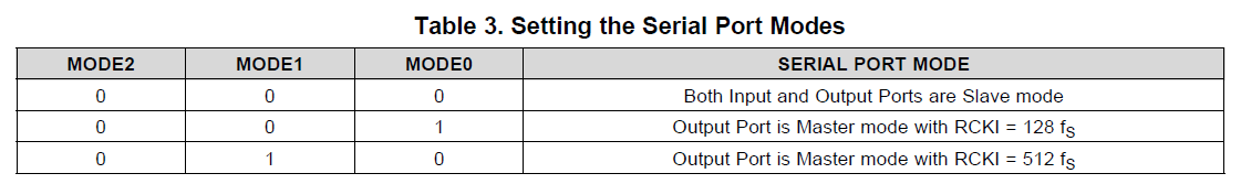
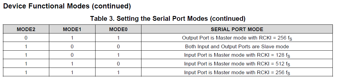
1. As the datasheet shows RCKI input is required in Master mode, and RCKI is not needed at "Both Input and Output ports are Slave mode"

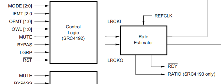
So, internal PLL can be clocked from LRCK or BCK in Slave mode. Is that correct?

2. /RDY become "L" when connect BCK and LRCK from input-side and output-side

However input-side BCK and LRCK is stopped, /RDY still keeps "L". 

Is this right behavior?

We are expecting internal "Rate estimator" can not get Rate data in this condition, then /RDY should be "H". 


Regards,

Mochizuki

  • Added drawings.


  • Hello,

    This inquiry based on urgent replacement activity because of competitors serious delivery issue.

    Could you give us your suggestion in this week?


    Additional question.

    3. On Table3, 000 and 100 are same "Both Input and Output ports are Slave mode" what is difference of those mode setting?


    Regards,

    Mochizuki

  • Hi Mochizuki,

    To answer your first question the device always requires an RCKI clock regardless of master or slave mode operation. This is used to generate the reference clock that is used by the rate estimator.

    I would expect that if both ports are operating in slave mode and the clocks are removed from either the input or the output the RDY pin should go high since the rate estimator relies on LRCKI, LRCKO, and the reference clock.

    There is no difference in the two slave mode settings. Essentially if MODE0 and MODE1 pins are both set low then the MODE2 pin is a 'don't care' pin.

    Best,

    Zak

  • Hi Zak,

    Thank you for your support and clear answer.


    In slave mode, RCKI rate is not specified on the register mode0,1,2.

    Then what is requirement of RCKI clock frequency.

    Should we follow the description on the datasheet as below?


    Figure 80 shows the reference

    clock connections and requirements for the SRC4192 and SRC4193 devices. The reference clock may operate

    at 128fS, 256fS, or 512fS, where fS are the input or output sampling frequency. The maximum external reference

    clock input frequency is 50 MHz.


    Here is the last question. Any kind of clock rate, like un-synchronized audio Fs clock up to 50MHz may be used at Slave mode?

    Actually our customer tried to use 24.00MHz and it looks work fine.


    Regards,

    Mochizuki

  • Hi Zak,

    Any update about RCKI clock rate? Can we use non-audio clock upto 50MHz.

    Our customer need to fix PCB layout to replace AK SRC device quickly.

    Regards,

    Mochizuki

  • Hi Mochizuki,

    I would recommend following the datasheet description you have included. Generally the RCKI needs to be a valid multiple of either the input or output sample rates, but it does not necessarily need to be synchronous with either of these ports. I would still not recommend any arbitrary RCKI rate though, it may work for some ranges but is not within the guidelines for operation so we can't really guarantee the device will always function as intended in this case.

    Best,

    Zak

  • Hi Zak,

    Thank you for your suggestion.

    Our customer pointed out that SRC4192 datasheet described ” Pin Compatible with the AD1896”

    And on AD1896 datasheet top page described as below.


    The master clock to the AD1896, MCLK, can be asynchronous to

    both the serial input and output ports.

    MCLK can be generated either off-chip or on-chip by the AD1896

    master clock oscillator. Since MCLK can be asynchronous to the

    input or output serial ports, a crystal can be used to generate

    MCLK internally to reduce noise and EMI emissions on the

    board. When MCLK is synchronous to either the output or input

    serial port, the AD1896 can be configured in a master mode where

    MCLK is divided down and used to generate the left/right

    and bit clocks for the serial port that is synchronous to MCLK.


    It seems MCLK can be asynchronous to the input or output serial ports.

    Also a crystal can be used to generate MCLK internally.

    So, they want to know SRC4192 can support both functionality?


    Regards,

    Mochizuki

  • Hello Zak,

    Our customer rush to replace the device to SRC4192 in current market situation.

    The engineer wants to make decision this morning in our time.

    Could you tell us the the best answer at this moment.

    Regards,

    Mochizuki

  • Hi Mochizuki,

    I'm sorry for the delay, please understand we are experiencing an extremely high volume of requests due to current circumstances in the audio community and we are trying to respond to everyone as quickly as we can!

    Although the SRC4192 is footprint compatible you may notice that pin 3 on AD1896 is MCLK_OUT whereas it is NC on SRC4192. This is because the SRC4192 does not have the CMOS oscillator circuitry necessary to accept a crystal input. Unfortunately this means they will need to use an external circuit to condition the crystal for input into the SRC4192 if they don't have a suitable MCLK available for RCKI.

    Best,

    Zak

  • Hello Zak,

    We appreciat for your reply under tough situation.

    About RCKI clock rate, on AD1896 MCLK can be used asynchronous to the input or output serial ports.
    No need to supply Audio clock like 128fs-512fs.
    Our customer had been confirmed this function using 24MHz non audio RCKI input to SRC4192.
    Can we accept this configuration?

    Regards,

    Mochziuki

  • Hi Mochizuki,

    This is also because the ADI device has an integrated PLL for generating the reference clock. I would strongly discourage you from referring to an ADI datasheet to design with a TI device...

    As I mentioned the RCKI does not need to be synchronous with the input/output clocks, but it should be a valid multiple as outlined in the datasheet. The reason 24MHz is working is most likely because 24.576MHz is a typical multiple for a 48kHz system and is likely 'close enough' for the device to operate. This still isn't in line with datasheet spec though so I would not recommend using an invalid clock multiple as this will inevitably degrade the margin of error in the sample rate estimation. There is generally a frequency range over which the part will operate, but we still recommend a fixed multiple because it ensure there is margin on either side for any jitter that may be present in the system.

    Best,

    Zak

  • Hi Zak,


    Our customer well understood the suggestion and follow your recommendation.


    Regards,

    Mochizuki