This thread has been locked.

If you have a related question, please click the "Ask a related question" button in the top right corner. The newly created question will be automatically linked to this question.

TPA6130A2: Recommended circuit for single-ended application

Part Number: TPA6130A2

Hello expert,

I have question for recommended application circuit for SE configuration.
I think our recommended circuit is EVM and it connected negative input to GND through coupling capacitor as following.

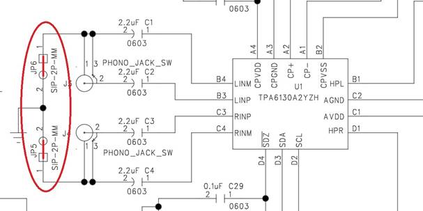
However, datasheet recommended to connect Positive input to GND as below.


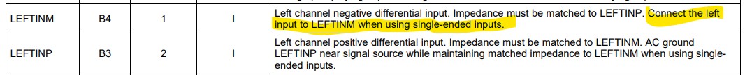
I found some related E2E thread but it caused confusion.
I guess TPA6130A2's internal simplified equivalent circuit is similar as below circuit.

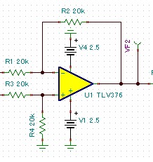
Therefore, there isn't spec difference (or non-inverting configuration(connect Neg in to GND) have slight better performance).
However, this thread said inverting connection have slight better performance than non-inverting connection.
Moreover, this thread said non-inverting configuration's output would be inverted from input signal.

So would you tell me which is TI's recommended circuit an which have better performance?
Also does this device output will be inverted under non-inverted configuration?


I'm waiting your reply.


Best regards,
Kazuki Kuramochi

  • Sorry I forgot to add E2E link.
    Please refer following thread.


    This thread

  • Hi, Kuramochi-san,

    Let me clarify the e2e threads in order to avoid confusion and future conflicts.

     As you correctly mentioned, the EVM uses the non-inverting input in single-ended configuration. For practical purposes, there's no difference on using the inverting or non-inverting input in single-ended configuration. The EVM actually works correctly with a good performance. However, the output will be inverted if the non-inverting input is used as single-ended configuration. That's why the datasheet recommends to use the inverting input if single-ended mode is used.

    But as mentioned in all the threads you shared, there's significant difference in the electrical specifications. So feel free to use the connection that gives you the phase you are looking for.

    Best regards,
    Luis Fernando Rodríguez S.

  • Hi Luis-san,

    Your swift reply is highly appreciated.

    I'd like to make sure about output phase.
    I suspect the output signal phase would be inverted under non-inverting connection.
    So I compared output phase by simulation using TINA TPA6132 model. Unfortunately I couldn't found model of TPA6130 but I believe TPA6132's relation between input and output phase is same as TPA6130.

    Following figure is simulation result and schematic and it showed non-inverting connection's output is in-phase as input signal.


    Sorry for bothering you but would you confirm output signal's phase again?


    Best regards,
    Kazuki Kuramochi

  • Hi, Kuramochi-san,

    I just performed some tests on the TPA6130A2EVM. It seems that the single-ended configuration it uses is correct. When using the non-inverting (LINP or RINP) input as single-ended (jumpers JP5 and JP6 inserted), I could get an output signal in phase.

    When I connected the signal to the M inputs and placed the P inputs AC-coupled to GND (jumpers JP5 and JP6 removed), I got an inverted output.

    Best regards,
    Luis Fernando Rodríguez S. 

  • Hi Luis-san,

    Thank you for your dedicated support.

    I understood that we need to use TPA6130A2 as non-inverted(INxP as signal source) if we need in-phase output.


    Thank you and best regards,
    Kazuki Kuramochi