This thread has been locked.

If you have a related question, please click the "Ask a related question" button in the top right corner. The newly created question will be automatically linked to this question.

TLV320ADC6140: Optimizing DRE setting

Part Number: TLV320ADC6140

Hi team,

I would like to understand the theory of operation to optimize DRE performance of TLV320ADC6140.

1. How does the "DRE maximum gain" setting affect the performance?

Could you give me a guide line to select the best setting?

2. How does DRE increase channel gain when the input level drops below DRE trigger threshold level?

It increases to DRE maximum gain, or it increases the channel gain linearly?

regards,

  • Is there any side effect or any points I need to take care if I use DRE function?

    regards,

  • Shinji-san,

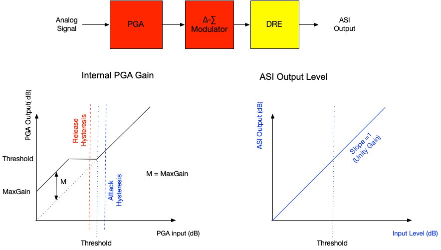
    The DRE follows the gain change curve shown on the left graph below (internal PGA Gain):

    Basically, as the input signal crosses the threshold, DRE increases the gain of the PGA that feeds the ADC, keeping the signal gain at the threshold level, until it reaches max gain. The DRE monitors the signal at an upsampled rate to track the signal as closely as possible. The gain on the output level is undone at the sample rate to maintain unity gain, thus the output level does not show any gain changes. This is shown on the top right graph: ASI Output Level.

    The DRE has a few parameters to control how fast it reacts to signal changes by attacking (decrease PGA gain when signal increases) or releasing (increase PGA gain when signal decreases). These are documented in the Application Note Using the Dynamic Range Enhancer in TLV320ADC5140/6140:

    • Release Time Constant: How fast the DRE circuitry responds with a PGA gain increase when the input signal falls below DRE threshold.
    • Attack Time Constant: How fast the DRE circuitry responds with a PGA gain decrease when the input signal rises above DRE threshold. 
    • Release Hysteresis: Amount of signal-level decrease in dB past the DRE threshold that forces the DRE to increase gain and start a release.
    • Attack Hysteresis: Amount of signal-level increase in dB past the DRE threshold that forces the DRE to decrease gain and start an attack.
    • Release Debounce: The number of consecutive input samples that falls below the DRE threshold after an attack event before the DRE starts a release and increases the PGA gain.
    • Attack Debounce: The number of consecutive input samples that rises above the DRE threshold after a release event before the DRE starts an attack and decreases the PGA gain.

    These parameters are not adjustable in the PPC3 GUI, but can be changed through I2C commands on the I2C monitor window of PPC3. The attached Excel spreadsheet will generate the corresponding register writes for these parameters.

    2474.DRE Calculator E2E.xlsx

    Momentary discontinuities can occur when there are large signal swings across the threshold. The above parameters can be used to minimize the discontinuities. For example, if the threshold is being crossed back and forth often, then use hysteresis and debounce to minimize unneeded consecutive multiple gain changes. To prevent multiple consecutive gain changes, set the release to be slow. For best results, keep the release 100-00x more than the attack and debounce times.

    Attack and release debounce settings depend on how often the input signal toggles between a low signal and a large signal. This prevents the DRE from oscillating between increasing and decreasing the gain, if a signal repeatedly alternates often between two levels.

    Hysteresis also prevents the DRE from oscillating between gains, the defaults values work well with music and speech. If the signal crosses over the threshold often, increase the hysteresis or decrease the threshold.

    If the threshold is too high with a large Max Gain, the input signal could be boosted significantly and clip at the ADC input, adding distortion. To prevent the input signal to the ADC from clipping, set the attack to be fast and the threshold set with enough margin. Also, set the threshold a 10-20 dBs less than the Max Gain.  Thus, keeping the threshold to around -54dB provides enough margin with Max Gain of 24dB. But setting a threshold of -24dB and Max Gain of 30dB can potentially boost past the ADC maximum input levels.  

    best regards,

      Pedro