This thread has been locked.

If you have a related question, please click the "Ask a related question" button in the top right corner. The newly created question will be automatically linked to this question.

TLV320AIC3254: TLV320AIC3254 telephony PCM interface

Part Number: TLV320AIC3254

Hi Gents, 

Hope you guys are all fine!

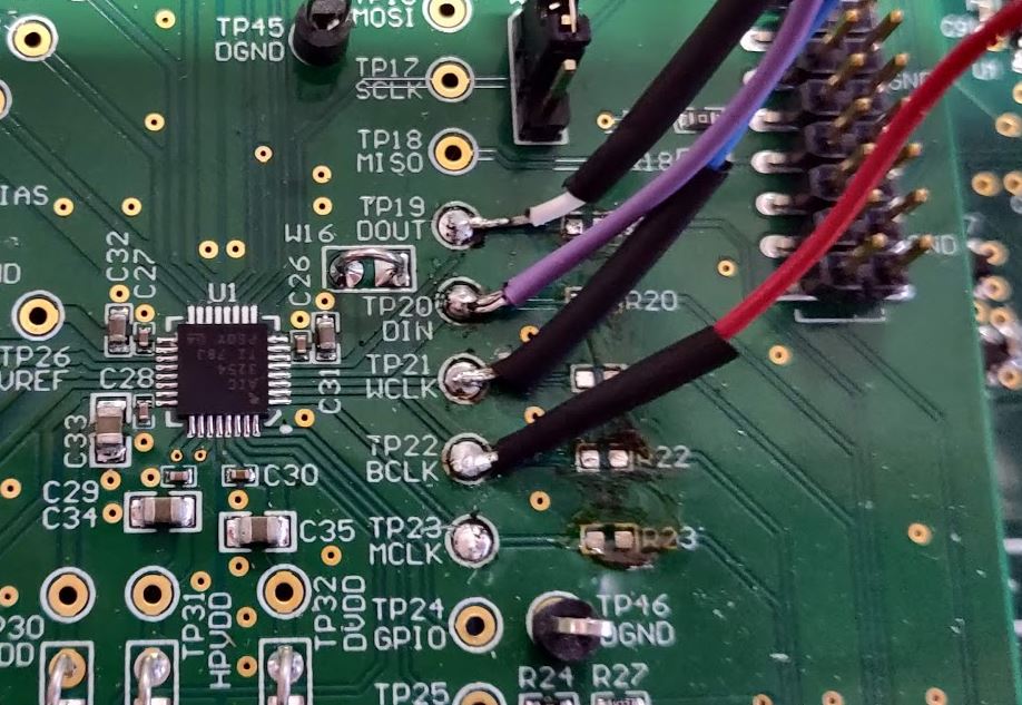
I'm using a TLV320AIC3254, connected to a phone network interface.

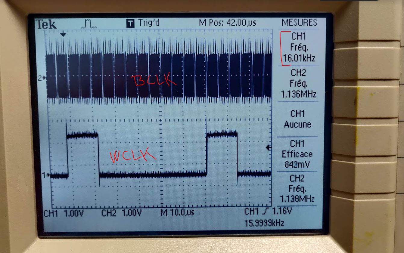
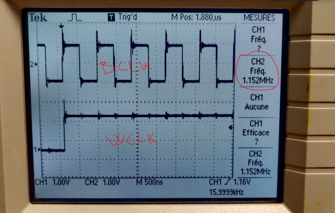
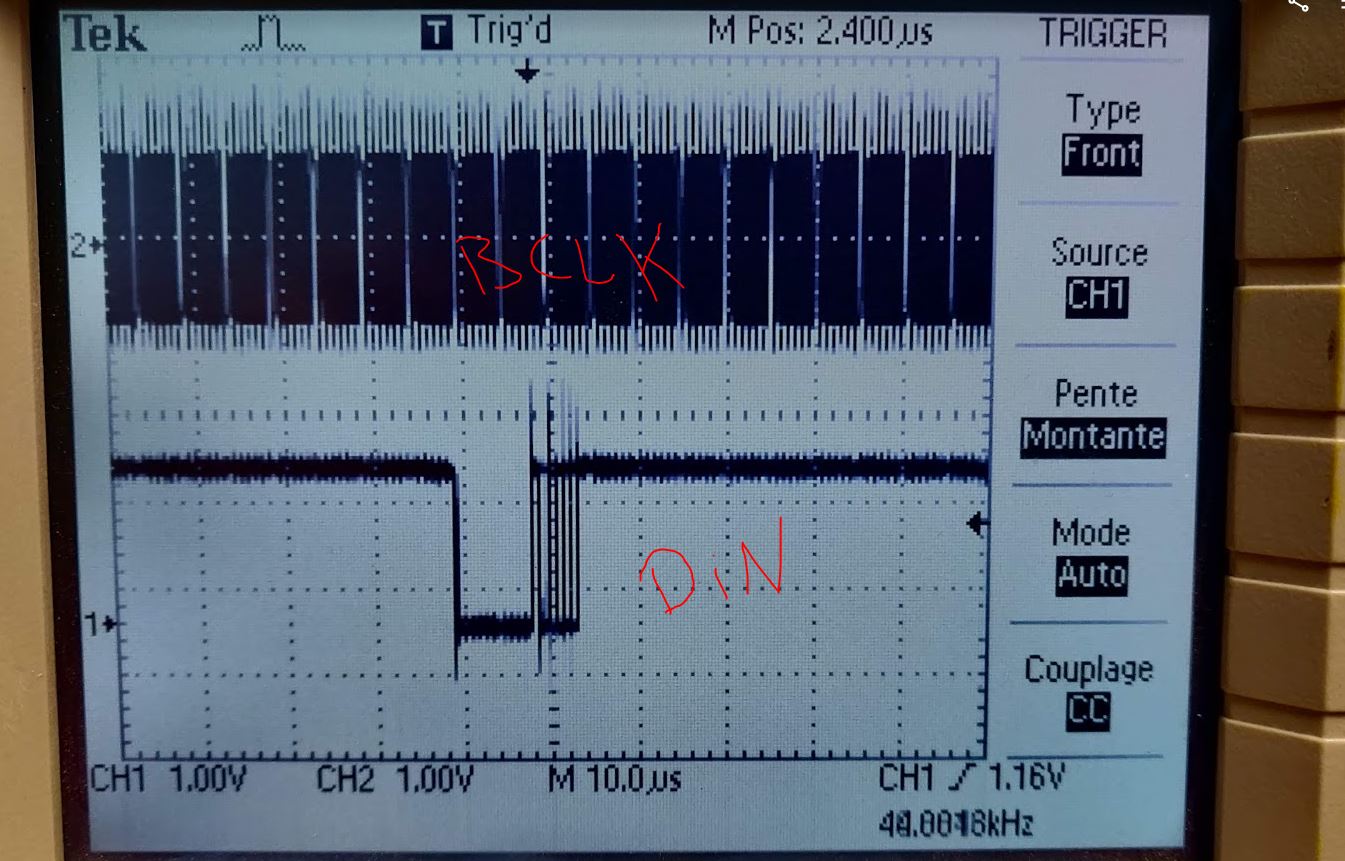
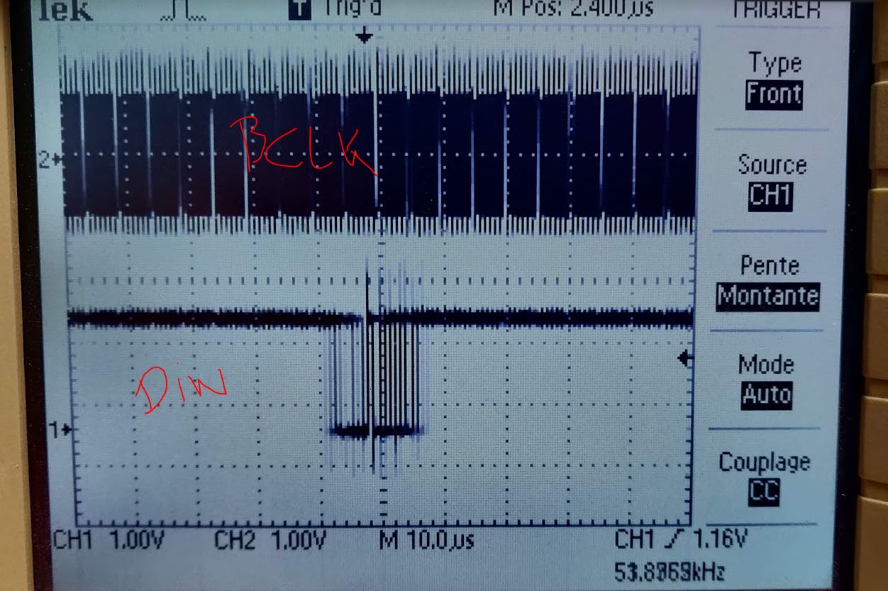
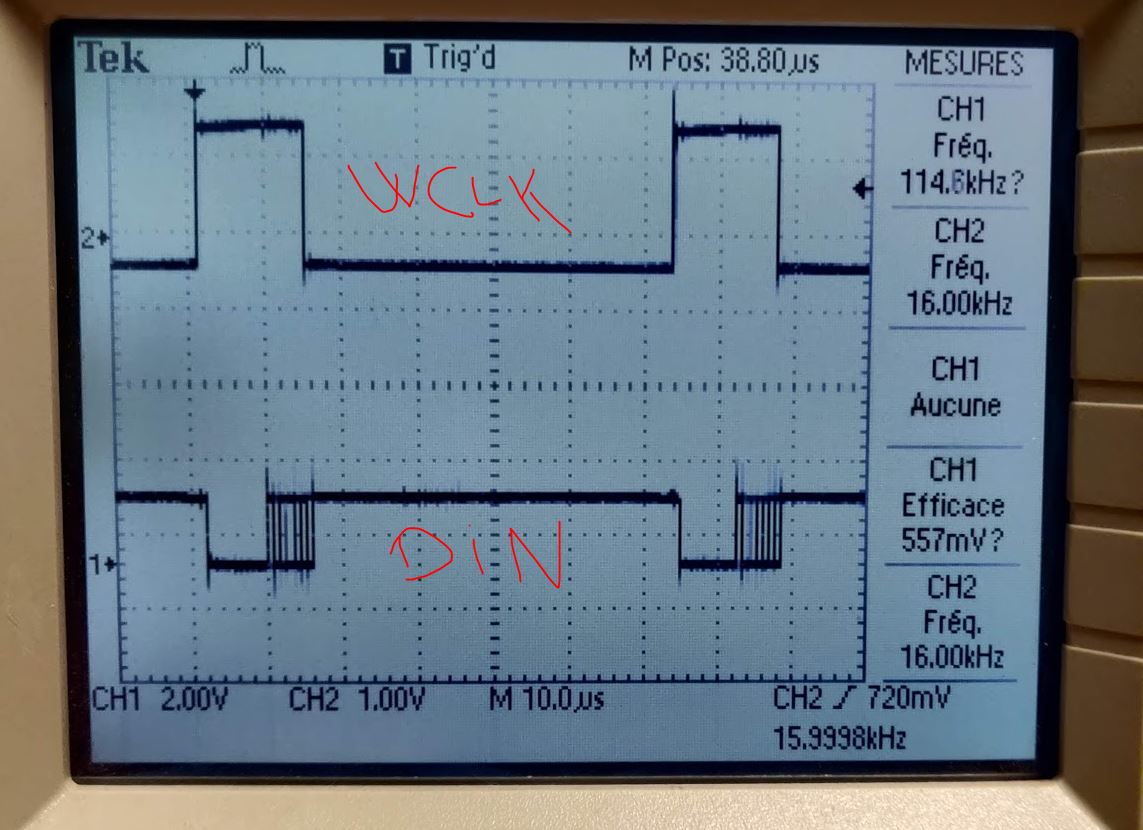
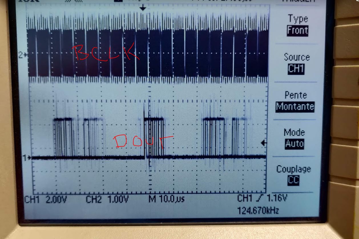
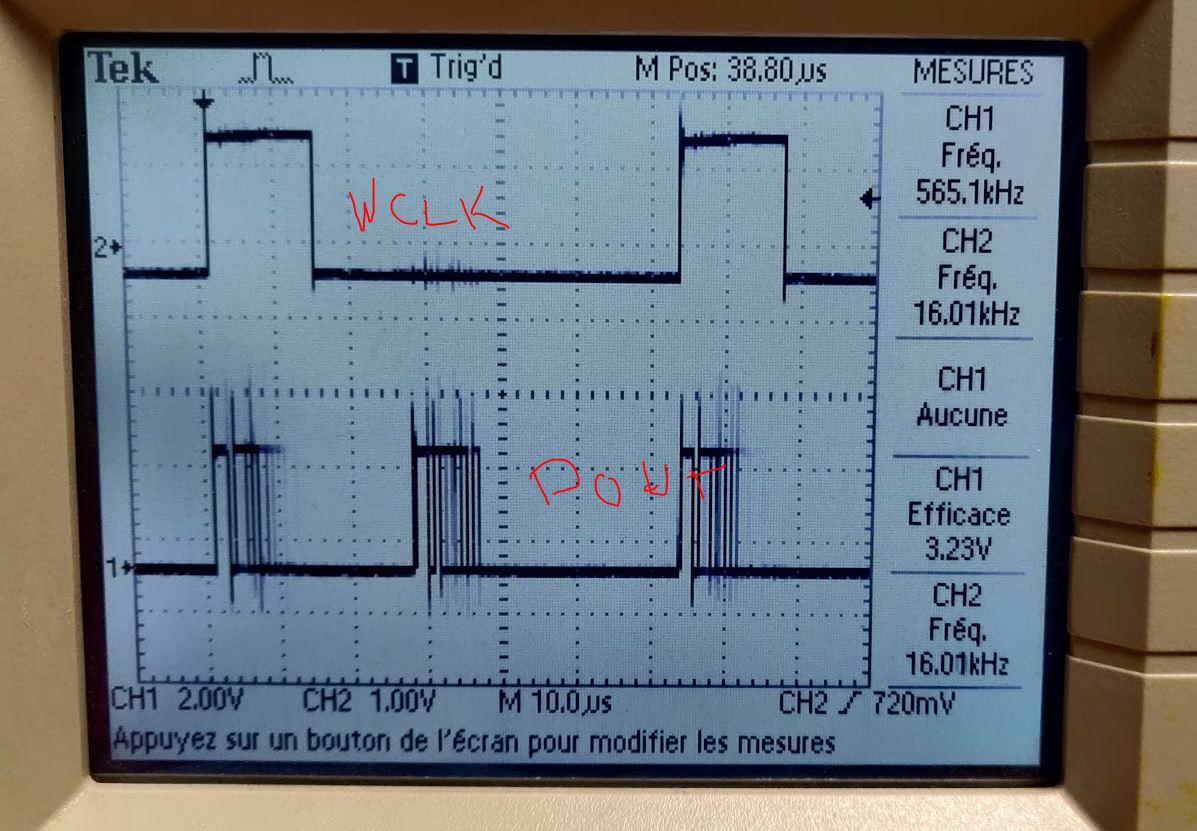
The network interface is setup as master, with a 16kHz word clock ( pulse, not square wave) and 16bits of data.

According to datasheet SLAS549D –SEPTEMBER 2008–REVISED NOVEMBER 2014 of the TLV320AI3254, on paragraph 10.3.6 Digital Audio IO Interface, i can read that the codec support I2S and PCM protocols, multi channels etc...

but I'm unable to find out where to configure them, how can i configure the following :

- Word clock as a pulse

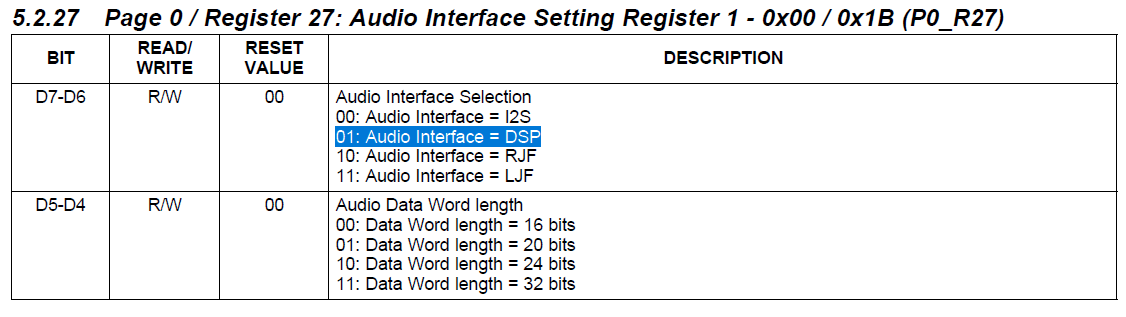
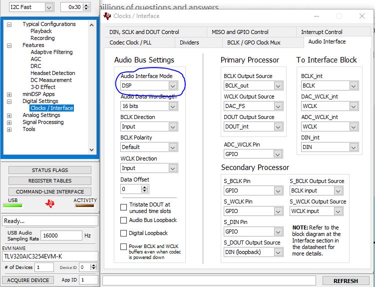
- activate the PCM interface ? should I use the I2S on the Page 0 register 27?

- select the number of channels, can I use 4 channels? in 


On the TLV datasheet I'm able to found the information about the datalengh ( Page 0 register 27), but i'm unable to find out if telephony PCM is I2S?

Can someone assit?

regards

Bruno

  • Hi Bruno,

    For this particular case, the Audio Interface should be set to DSP mode (Page 0, Register 27). The word length can be selected using D5-D4 bits of the same register.

    Section 2.6 Audio Digital IO Interface of the Applications Reference Guide (https://www.ti.com/lit/slaa408a) describes all the interface options supported by the device. AIC3254 can receive two channels and transmit two channels. The timing and channel slot selection details are available in Section 2.6.4 DSP Mode.

    Please write back to us if you need more info.

    Best Regards.

    Best Regards,

  • Hi Diljith, 

    thanks for your reply, I will try, another related question, as I'm using a purepart studio process flow, do I need to change something on the I2S output configuration to switch onto DSP mode or only changing the Register 27 is enought?

  • None of the parameters of the I2S component in PPS have to be changed.

    The change in Register 27 has to be done through SystemSettingCode.

    There may be other changes required depending on how you plan to connect the external device.

    The EVM User's Guide and the Application Reference Guide are essential references for setting this up.

    The J14 connector on the motherboard can be used for interfacing. If you plan to use MCLK also from the external device and the MCLK frequency is same as the MCLK frequency on the EVM then no other change is required. However if MCLK Is not the same or if AIC3254 has to run using BCLK (without MCLK) then the clock-tree has to be changed to run the PLL from BCLK.

    If you need more info., please write back.

    Best Regards.

  • just for information about the hardware and software used.

    I'm using the EVM as an hardware connected to my phone interface in PCM using the J14 connector.

    I'm using the process flow bellow and once EVM is running changing some parameter using AIC3254 ( as audio itnerface mode to DSP instead of I2S).

    The phone interface connected to the EVM is set as master genetrating a WCLK of 16kHz and a BCLK of 1.152MHz.

    using AIC3254 i've set the following :

    - audio interface mode = DSP (p0_r27_b7-6)

    - BCLK direction as an input  (p0_r27_b3)

    - WCLK direction as an input   (p0_r27_b2)

    but do I need to change something on the Clocks/interface tabs ?

    whats do you mean by:

    "However if MCLK Is not the same or if AIC3254 has to run using BCLK (without MCLK) then the clock-tree has to be changed to run the PLL from BCLK."

    the MCLK is from the EVM, the only connection with my phone interface is DIN/DOUT/WCLK and BCLK

    Regards

    Bruno

  • Hi Bruno,

    By default, MCLK is used by the device to generate its internal clocks (e.g. ADC, DAC modulator clocks).

    However, the device can also generate the internal clocks from the BCLK.

    The MCLK coming from the EVM cannot be used as it is not synchronous with the BCLK and FS coming from the network interface.

    Therefore, we would have to change the PLL settings to generate the ADC and DAC clocks from BCLK.

    The PLL settings for generating the internal clocks have to be arrived at.

    Please use the PLL calculator from  https://e2e.ti.com/support/audio/f/6/t/946529 for this purpose.

    The other reference that comes in handy is the Applications Reference Guide (ti.com/lit/slaa408a).

    Best Regards.

  • I've used the excel sheet to adjuste the PLL settings i've got the following result, seems to match with my PCM phone interface.

    by the way audio is very noisy voice not understandable, i've found this shems on the PCM phone interface, seems that 4 channels are sent, and the TLV is supposed to work with 2 channels, is there a chance to configure the TLV to match with this frame shape ? i mean 4 channels of 16bits? 

    assuming WCLK to be 16kHz and a BCLK of 1.152Mhz we've got 4 channels of 16bits each.


  • AIC3254 will only pick two channels from the bus. Even if four channels are sent. By default it will pick the first two.

    Additional channels would not cause any problems as such.

    Would you be able to capture all the signals - MCLK, BCLK, WCLK, DIN and DOUT - on the J14 header and share it with us?

    Also share the configuration settings. I shall review them and send you feedback.

    Best Regards.

  • Hi Diljith, 

    good to know that firt 2 channels are taken into account or data getting IN the TLV, but what is the status of data going OUT the TLV?

    First of all it seems my pictures are not well added to my messages, so my process flow is :

    then on AIC i've tunned it with the following parameters :

    on the PLL i've fill the BCLK ( coming from my phone PCM interface as a source for PLL_CLKIN  change the PLL setting to get 4.608Mhz on CODEC_CLKIN :

    on dividers I've fill the following parameters to get DAC/ADC_FS set at 16kHz and DAC/ADC_CLK set at 1.152Mhz, to match with BLCK and WCLK of my  PCM phone interface :

    on the dev kit board I've removed the resistor R19 to R23 and connect the PCM signals directly from the TLV to the PCM phone interface using the TP to avoid any interference from the mother board (but maybe this is a mistake):

    regarding signal shape i've got WCLK and BCLK like this :

    DIN and BCLK  when nobody is talking :

    DIN and BCLK  when talking :

    DIN and WCLK when nobody is talking :

    BCLK and DOUT  :

    WCLK and DOUT :

  • The ADC_CLK and DAC_CLK are too low for DSP operation.

    I would suggest making the following changes

    1. Increase J from 4 to 40 so that the PLL output its ~46 MHz.

    2. Reduce MDAC and MADC to 40 so that ADC and DAC modulator clocks are at 1152 kHz.

    All the other clock-tree parameters can remain the same.

    Best Regards.

  • Hi Diljith, 

    changing the PLL settings according to your advise is working on the following way, now I don't know why it is ony working on one side.

  • Hi Bruno,

    Please check the DAC Clocks - DAC_CLK, DAC_MOD_CLK and DAC_FS - and see if they are all powered up and the expected frequency.

    After that, as a debug step, please add a tone generator to the process flow's existing playback path (shown below) and mix it with the LR mix and send the final mix to the interpolator. Check if the tone is heard on the headphones with this new flow. 

    Best Regards,

  • Hi Dijith, 

    i've tried yto use the tone generator to test the line output using this simple process flow with a board sampling rate of 16kHz :

    - i've launched it with a 1.152MHz BCLK for PLL_CLK_IN with the following parameters on AIC3254 and i've got no audio on line out (RDAC and LDAC are routed to LOL and LOR) :

    - i've tried same process flow but this time i've used the MCLK of the EVM of 11.28MHz and the following parameters on AIC and it is working :

    I assume there is something not well configured, and the DSP is not working properly, what is the relation between the board rate when generating the process on GDE (I'm using 16kHz) and the DAC_FS and ADC_FS?

    for example my PCM is working at 16kHz of frame sync, and 1.152Mhz of BCLK what should be the values for the DAC/ADC_MOD and DAC/ADC_FS? are they related?

    thanks for your support Diljith, i'm not used to codec sorry for my lack of knowledge.

    Regards

  • Everything you are doing seems proper. I am not sure why the Tx path is not working.

    Could you give me a register dump of all the Page 0 and Page 1 registers?

    I will examine and get back to you.

    Best Regards.

  • HI Diljith, 

    Please find the files attached, resgister or page 1 and 0.TI_PAGE0.xlsxTI_PAGE1.xlsx

  • Hi Bruno,

    Everything looks good. The clock setting is correct, the DACs are powered, up, the DAC output is routed to HPL/R and LOL/R and all four of them are powered up and un-muted. I can't think of a reason why the output would be zero other than the fact the input is also zero. But since we are internally generating the tone, that is also ruled out. Please send me a picture of the SW2 switch and also send me your test pfw (with the tone gen). I will debug at my end.

    Best Regards.

  • Hi Diljith,

    Please find a picture of SW2 , by the way, i remove R19, R20, R21 and R22

    Best Regards,

    Bruno Henriques

  • SW.4 should be set to high for external interfacing. Please try with this change.

    Best Regards.