This thread has been locked.

If you have a related question, please click the "Ask a related question" button in the top right corner. The newly created question will be automatically linked to this question.

TLV320AIC3254: Noise After 8 kHz

Part Number: TLV320AIC3254
Other Parts Discussed in Thread: CC3200AUDBOOST

Hi

We use TI CC2642 + TI AIC3254 to design our project. Regarding AIC3254, the input a microphone, the output is a headphone-out and the sample rate is 8KHz.

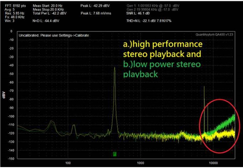
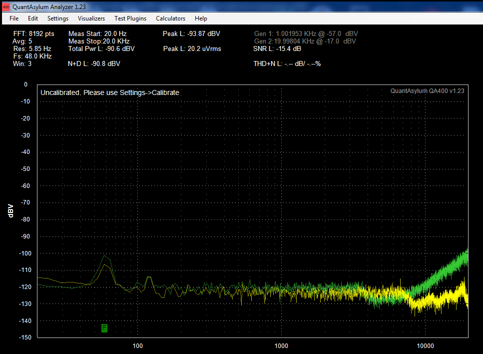
Currently, we have encountered some noise problems above 8KHz, you could refer to following figure in detail.

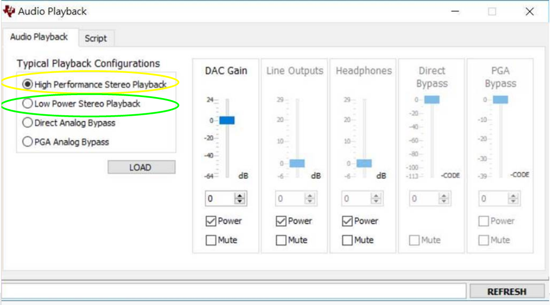
We conducted some experiments on AIC3254 EVM, we found the issue seems to be related to "High performance playback"& low power playback. you could refer to the following figure.

Do you have any suggestion to us?

We also uploaded our AIC3254 configuration as shown below:

AudioCodec_pageSelect(TI3254_PAGE_0);
AudioCodec_regWrite(TI3254_AUDIO_IF_1_REG, 0x00);

AudioCodec_pageSelect(TI3254_PAGE_0);
AudioCodec_regWrite(TI3254_CLK_MUX_REG, 0x03);       // PLL Clock is CODEC_CLKIN
AudioCodec_regWrite(TI3254_CLK_PLL_P_R_REG, 0x80 | 0x10 | 0x02);    // PLL is powered up, P=1, R=2
AudioCodec_regWrite(TI3254_CLK_PLL_J_REG, 0x008);     // J=8
AudioCodec_regWrite(TI3254_CLK_PLL_D_MSB_REG, 0x00); // D = 0000
AudioCodec_regWrite(TI3254_CLK_PLL_D_LSB_REG, 0x00); // D = 0000

AudioCodec_regWrite(TI3254_CLK_NDAC_REG, 0x80 | 0x01);      // NDAC divider powered up, NDAC = 1
AudioCodec_regWrite(TI3254_CLK_MDAC_REG, 0x80 | 0x04);      // MDAC divider powered up, MDAC = 4
AudioCodec_regWrite(TI3254_DAC_OSR_MSB_REG, 0x00);   // DOSR = 0x0080 = 128
AudioCodec_regWrite(TI3254_DAC_OSR_LSB_REG, 0x80);   // DOSR = 0x0080 = 128

AudioCodec_regWrite(TI3254_CLK_NADC_REG, 0x80 | 0x01);      // NADC divider powered up, NADC = 1
AudioCodec_regWrite(TI3254_CLK_MADC_REG, 0x80 | 0x04);      // MADC divider powered up, MADC = 4
AudioCodec_regWrite(TI3254_ADC_OSR_REG, 0x80);       // AOSR = 128 ((Use with PRB_R1 to PRB_R6, ADC Filter Type A)


AudioCodec_pageSelect(TI3254_PAGE_1);        //Select Page 1
AudioCodec_regWrite(TI3254_PWR_CTRL_REG, 0x08);  // Disabled weak connection of AVDD with DVDD
AudioCodec_regWrite(TI3254_LDO_CTRL_REG, 0x01);  // Over Current detected for AVDD LDO
AudioCodec_regWrite(TI3254_ANALOG_IP_QCHRG_CTRL_REG, 0x32); // Analog inputs power up time is 6.4 ms
AudioCodec_regWrite(TI3254_REF_PWR_UP_CTRL_REG, 0x01);   // Reference will power up in 40ms when analog blocks are powered up

BR

Trevor

  • Hi Trevor,

    How are you routing the mic to the analog output?

    Are you using the analog bypass path (direct)  or PGA bypass or are you routing ADC output to DAC input ?

    Diljith

  • Hi Diljith

    Regarding our routing setting for ADC & DAC as shown below:

    #For DAC Routing
    AudioCodec_pageSelect(TI3254_PAGE_0);    //Select Page 0
    // ##Configure Processing Blocks
    AudioCodec_regWrite(TI3254_DAC_SIG_P_BLK_CTRL_REG, 0x2);  // DAC Signal Processing Block PRB_P2
    
    AudioCodec_pageSelect(TI3254_PAGE_1);    // Select Page 1
    //De-pop: 5 time constants, 6k resistance
    AudioCodec_regWrite(TI3254_HP_DRV_START_UP_CTRL_REG, 0x25);  // Headphone ramps power up time is determined with 6k resistance,
                                                                                                             // Headphone ramps power up slowly in 5.0 time constants
    
    //Route LDAC/RDAC to HPL/HPR
    AudioCodec_regWrite(TI3254_HPL_ROUTING_SEL_REG, 0x08);   // Left Channel DAC reconstruction filter's positive terminal is routed to HPL
    AudioCodec_regWrite(TI3254_HPR_ROUTING_SEL_REG, 0x08);   // Left Channel DAC reconstruction filter's negative terminal is routed to HPR
    AudioCodec_regWrite(TI3254_OP_DRV_PWR_CTRL_REG, 0x30);// HPL and HPR is powered up
    //Unmute HPL/HPR driver, 0dB Gain
    AudioCodec_regWrite(TI3254_HPL_DRV_GAIN_CTRL_REG, 0x00);     // HPL driver is not muted, HPL driver gain is 0dB
    AudioCodec_regWrite(TI3254_HPR_DRV_GAIN_CTRL_REG, 0x00);     // HPR driver is not muted, HPL driver gain is 0dB
    
    AudioCodec_pageSelect(TI3254_PAGE_0);        //Select Page 0
    //DAC => 64dB
    AudioCodec_regWrite(TI3254_LEFT_DAC_VOL_CTRL_REG, 0x80);     // Digital Volume Control = 64.0dB silent Note: As per data sheet its reserved but on setting this value there is silent
    AudioCodec_regWrite(TI3254_RIGHT_DAC_VOL_CTRL_REG, 0x80);    // Digital Volume Control = 64.0dB silent Note: As per data sheet its reserved but on setting this value there is silent
    AudioCodec_pageSelect(TI3254_PAGE_0);        //Select Page 0
    //Power up LDAC/RDAC
    AudioCodec_regWrite(TI3254_DAC_CHANNEL_SETUP_1_REG, 0xD6);   // Left and Right DAC Channel Powered Up
                                                                                                             // Left DAC data Left Channel Audio Interface Data
                                                                                                             // Right DAC data is Left Channel Audio Interface Data
                                                                                                             // Soft-Stepping is disabled
    //Unmute LDAC/RDAC
    AudioCodec_regWrite(TI3254_DAC_CHANNEL_SETUP_2_REG, 0x00);   // When Right DAC Channel is powered down, the data is zero.
                                                                                                             // Auto Mute disabled
                                                                                                             // Left and Right DAC Channel not muted
                                                                                                             // Left and Right Channel have independent volume control
    

    # For ADC Routing
    AudioCodec_pageSelect(TI3254_PAGE_8);    // Select Page 8
    AudioCodec_regWrite(TI3254_ADC_ADP_FILTER_CTRL_REG, 0x04);   // Adaptive Filtering enabled for ADC
    AudioCodec_pageSelect(TI3254_PAGE_0);        //Select Page 0
    AudioCodec_regWrite(TI3254_ADC_SIG_P_BLK_CTRL_REG, 0x2); // ADC Signal Processing Block PRB_P2
    AudioCodec_pageSelect(TI3254_PAGE_1);     //Select Page 1
    AudioCodec_regWrite(TI3254_MICBIAS_CTRL_REG, 0x40);
    AudioCodec_regWrite(TI3254_LEFT_MICPGA_P_CTRL_REG, 0x00);
    AudioCodec_regWrite(TI3254_LEFT_MICPGA_N_CTRL_REG, 0x40);
    AudioCodec_regWrite(TI3254_RIGHT_MICPGA_P_CTRL_REG, 0x40);
    AudioCodec_regWrite(TI3254_RIGHT_MICPGA_N_CTRL_REG, 0x40);
    AudioCodec_regWrite(TI3254_FLOAT_IP_CTRL_REG, 0x40);
    
    //make channel gain 0dB, since 20K input
    //impedance is used single ended
    AudioCodec_regWrite(TI3254_LEFT_MICPGA_VOL_CTRL_REG, 0x00);  // 0.0dB
    
    //Unmute Right MICPGA, Gain selection of 6dB to
    //make channel gain 0dB, since 20K input
    //impedance is used single ended
    AudioCodec_regWrite(TI3254_RIGHT_MICPGA_VOL_CTRL_REG, 0x00); // 0.0dB
    AudioCodec_pageSelect(TI3254_PAGE_0);     //Select Page 0
    AudioCodec_regWrite(TI3254_LEFT_ADC_VOL_CTRL_REG, 0x68);     // -12dB
    AudioCodec_regWrite(TI3254_RIGHT_ADC_VOL_CTRL_REG, 0x68);    // -12dB
    AudioCodec_pageSelect(TI3254_PAGE_0);    // Select Page 0
    //Power up LADC/RADC
    AudioCodec_regWrite(TI3254_ADC_CHANNEL_SETUP_REG, 0xC0); // Left and Right Channel ADC is powered up
    
    //Unmute LADC/RADC
    AudioCodec_regWrite(TI3254_ADC_FINE_GAIN_ADJ_REG, 0x00); // Left and Right ADC Channel Un-muted. Left and Right ADC Channel Fine Gain = 0dB,
            

    BR

    Trevor

  • Hi Trevor,

    I am not yet clear at which point you are observing the noise.

    Going by the comments, it appears that the MIC data is routed to I2S output and I2S input is routed to DAC and headphones.

    I gather that you are measuring the frequency response at the headphone outputs.

    Is that correct? If so, then the input is not the mic. data but rather the data that you are sending on I2S input.

    Can you clarify?

    Best Regards.

  • Hi Diljith,

    Regarding Noise, I think we can focus on TLV320AIC3254EVM-K. We use the AIC3254 CS to configure audio playback, you could see the following figure, you can see the yellow circle and the green circle. it represents the "High Performance Stereo Playback" & "Low Power Stereo Playback".  

    We perform spectrum measurements on these two settings separately, the spectrum results are shown in the figure below, I think you could ignore the input source(input source is 400Hz tone), because we are focusing on frequency band after 8KHz. Regarding the spectrum figure, there are two setting result, the yellow line represents "High Performance Stereo Playback", the green line represents "Low Power Stereo Playback", you can observe that the amplitude of green line will become larger in the frequency band after 8KHz.(The yellow line doesn't have this issue). Could we discuss this problems first? 

    Regarding your questions: "

    I gather that you are measuring the frequency response at the headphone outputs.

    Is that correct? If so, then the input is not the mic. data but rather the data that you are sending on I2S input.

    Can you clarify?"

    >>>>>>>>>>>>>>>>>>>>>>>>>>>>>>>

    Yes, we are measuring the the frequency response at the headphone outputs. we only copy the input data without any data processing on CC26x2 side.

    MIC - > AIC3254 -> I2S IN -> CC26x2 -> I2S OUT -> AIC3254 -> HP

    Thanks.

    BR

    Trevor

  • Hi Trevor,

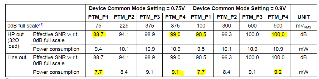
    AIC3254 device has a few knobs in the DAC & ADC to trade-off performance for power. These knobs are made available as Power Tune Modes (PTM).

    Shown below is a comparative performance for different DAC PTM settings using Interpolation Filter B (the setting that you have used).

    Refer to section 2.5.0.3 for comparisons of PTM mode performances for other device operating conditions.

    The high performance mode uses PTM_P4 (better SNR and hence lower noise) and the low-power mode uses PTM_P1 (poorer SNR and hence higher noise).

    I hope that answers your concern.

    Best Regards.

  • Hi Diljith,

    Thanks for your information.

    Regarding our AIC3254 configuration we provided before, if we want to enable the "High Performance Stereo Playback"(PTM_P4), could you guide us how to modify AIC3254 configuration?.

    Thanks.

    BR

    Trevor

  • Hi Trevor,

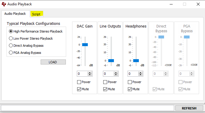
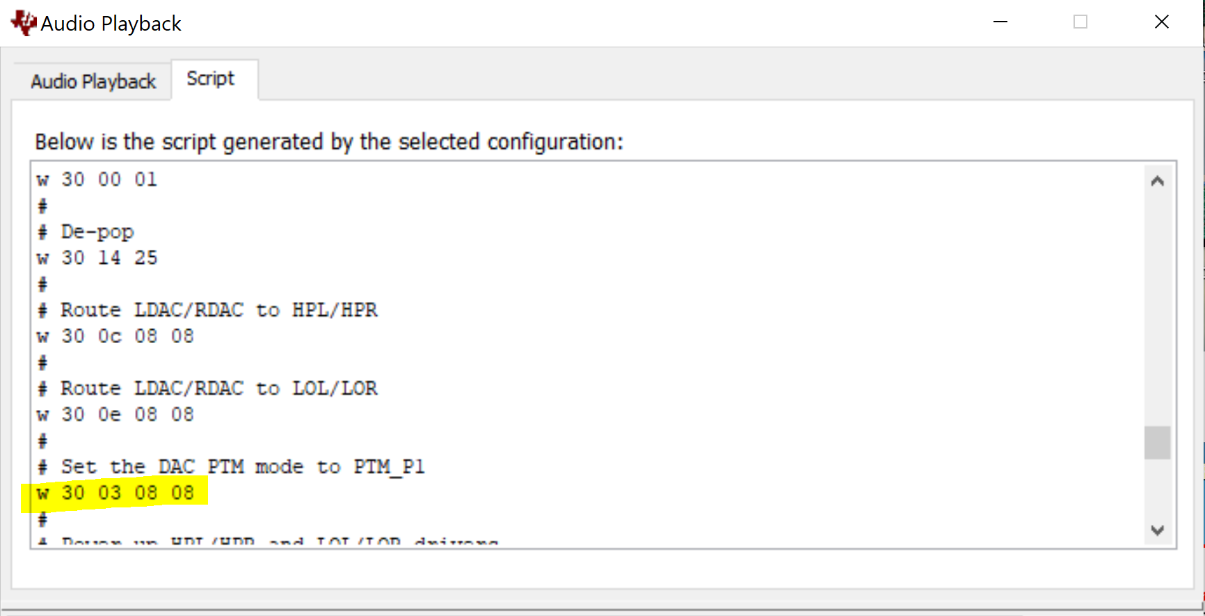
    The device register writes for each mode on the GUI is available in the Scripts tab. I have attached it here for your convenience.

    Best Regards.

    https://e2e.ti.com/cfs-file/__key/communityserver-discussions-components-files/6/AIC3254-HP-Playback

  • Hi Diljith,

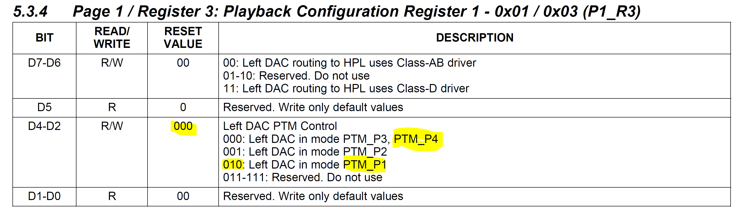
    Regarding PTM_P4 setting,  the related registers are in Page 1 / Register 3: Playback Configuration Register 1 - 0x01 / 0x03 (P1_R3) & Page 1 / Register 4: Playback Configuration Register 2 - 0x01 / 0x04 (P1_R4).

    But I can't find the relevant settings in your configuration file. Can you help to check it?

    BR

    Trevor

  • Hi Trevor,

    PTM_P4 is the default power-tune mode for the LDAC and RDAC. It is not part of the high-performance playback script. It is part of the low-power playback script. It is highlighted in the two pictures below.

    I don't see any updates to the PTM default register in the configuration that you shared. I would try to read back the register to be sure.

    Best Regards.

  • Hi Diljith,

    Thanks for your information, we don't make any changes to the PTM register. The AIC3254 default is set to PTM_P4, so I think this issue doesn't related to PTM.

    We tried to change the sampling rate from 8000 to 16000, we got a smaller noise after 8KHz. you could refer to the following figure in detail.(Green: 8K ; Yellow: 16K ).

    Do you have any ideas or suggestions?

    #For 8K Setting

                 AudioCodec_pageSelect(TI3254_PAGE_0);
    
                 AudioCodec_regWrite(TI3254_CLK_MUX_REG, 0x03);       // PLL Clock is CODEC_CLKIN
                 AudioCodec_regWrite(TI3254_CLK_PLL_P_R_REG, 0x80 | 0x10 | 0x02);    // PLL is powered up, P=1, R=2
                 AudioCodec_regWrite(TI3254_CLK_PLL_J_REG, 0x008);     // J=8
                 AudioCodec_regWrite(TI3254_CLK_PLL_D_MSB_REG, 0x00); // D = 0000
                 AudioCodec_regWrite(TI3254_CLK_PLL_D_LSB_REG, 0x00); // D = 0000
    
                 AudioCodec_regWrite(TI3254_CLK_NDAC_REG, 0x80 | 0x01);      // NDAC divider powered up, NDAC = 1
                 AudioCodec_regWrite(TI3254_CLK_MDAC_REG, 0x80 | 0x04);      // MDAC divider powered up, MDAC = 4
                 AudioCodec_regWrite(TI3254_DAC_OSR_MSB_REG, 0x00);   // DOSR = 0x0080 = 128
                 AudioCodec_regWrite(TI3254_DAC_OSR_LSB_REG, 0x80);   // DOSR = 0x0080 = 128
    
                 AudioCodec_regWrite(TI3254_CLK_NADC_REG, 0x80 | 0x01);      // NADC divider powered up, NADC = 1
                 AudioCodec_regWrite(TI3254_CLK_MADC_REG, 0x80 | 0x04);      // MADC divider powered up, MADC = 4
                 AudioCodec_regWrite(TI3254_ADC_OSR_REG, 0x80);       // AOSR = 128 ((Use with PRB_R1 to PRB_R6, ADC Filter Type A)
     

    #For 16K Setting

                   AudioCodec_pageSelect(TI3254_PAGE_0);
    
                    AudioCodec_regWrite(TI3254_CLK_MUX_REG, 0x13);       // PLL Clock is CODEC_CLKIN
                    AudioCodec_regWrite(TI3254_CLK_PLL_P_R_REG, 0x80 | 0x10 | 0x04);    // PLL is powered up, P=1, R=4
                    AudioCodec_regWrite(TI3254_CLK_PLL_J_REG, 0x30);     // J=48
                    AudioCodec_regWrite(TI3254_CLK_PLL_D_MSB_REG, 0x00); // D = 0000
                    AudioCodec_regWrite(TI3254_CLK_PLL_D_LSB_REG, 0x00); // D = 0000
    
                    AudioCodec_regWrite(TI3254_CLK_NDAC_REG, 0x80 | 0x04);      // NDAC divider powered up, NDAC = 4
                    AudioCodec_regWrite(TI3254_CLK_MDAC_REG, 0x80 | 0x04);      // MDAC divider powered up, MDAC = 4
                    AudioCodec_regWrite(TI3254_DAC_OSR_MSB_REG, 0x01);   // DOSR = 0x0180 = 384
                    AudioCodec_regWrite(TI3254_DAC_OSR_LSB_REG, 0x80);   // DOSR = 0x0180 = 384
    
                    AudioCodec_regWrite(TI3254_CLK_NADC_REG, 0x80 | 0x0C);      // NADC divider powered up, NADC = 12
                    AudioCodec_regWrite(TI3254_CLK_MADC_REG, 0x80 | 0x04);      // MADC divider powered up, MADC = 4
                    AudioCodec_regWrite(TI3254_ADC_OSR_REG, 0x80);       // AOSR = 128 ((Use with PRB_R1 to PRB_R6, ADC Filter Type A)


    Thanks

    BR

    Trevor

  • The out of band frequency response could be different for different sampling rates. It could also be because of incorrect configuration.

    I would first check the idle channel response on TI CC2642 + TI AIC3254 and compare that to the EVM response.

    Both for 8 kHz and 16 kHz. If there are differences between the two setups, then it would point to configuration differences. 

    In most cases it is the clock-tree (OSR, DSP rate etc.).

    Let me know your observations.

    Best Regards.

  • Hi Diljith,

    Excuse me, we don't know what an idle channel is. Could you provide some description for idle channel?

    We also check the AIC3254 EVM with "USBMODEVMxxxx_8KHZ.BIN" firmware. It has no out-of-band frequency noise.

    Do you know which configuration of this firmware? How to use AIC3254 CS to dump PLL clock configuration for AIC3254 EVM? How to apply our PLL configuration to AIC3254 EVM?

    Thanks.

    BR

    Trevor

  • Hi Trevor,

    A channel is said to be idle when there is no input to the channel. Idle channel behavior can be obtained by either grounding the input terminals or playing zeros (silence). Some systems introduce dither while playing zeros, so it may not be equivalent to grounding the input. But for our measurements we should be ok with either.

    Please try the following and let us look at the response and PLL settings.

    1. Use EVM --> High Performance Playback mode --> Play silence --> measure the frequency response of headphone output (up to 24 kHz).

    2. Use CC2642 setup --> configure device --> Play silence --> measure the frequency response of headphone output (up to 24 kHz).

    Please note down the PLL settings for both. The register values that are relevant are - PLL input, P, R, J, D, MDAC, MADC, NDAC and NADC.

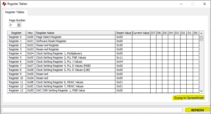
    On the EVM, the register settings can be dumped to a spreadsheet using the "Register Tables"  interface.

    Best Regards.


  • Hi Diljith,

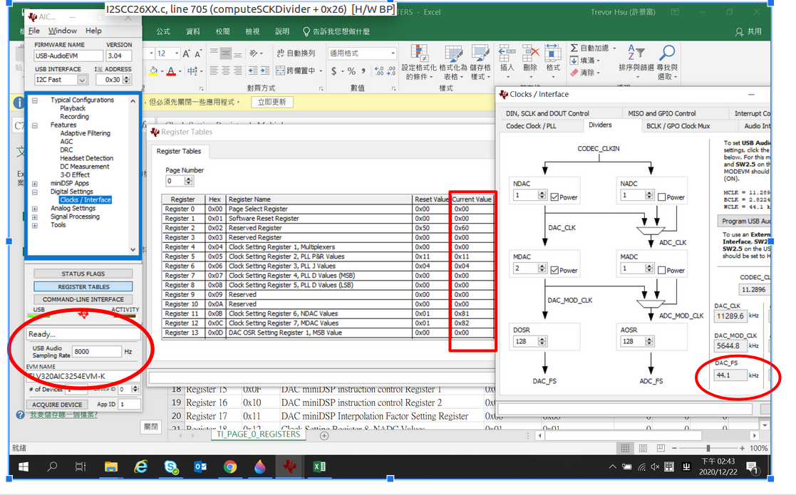
    Regarding AIC3254 EVM, although we have updateed the 8K firmware to EVM, the register setting of PLL still show the 44.1K settings.

    But we measure the waveform, the WCLK is 8K and BCLK is 512Khz.

    BR

    Trevor

  • Hi Diljith,

    We compared the waveform for AIC3254 EVM and "CC3200AUDBOOST", we found the BCLK is different, about AIC3254 EVM is 512KHz and the CC3200AUDBOOST is 256KHz.

    We also change the CC3200AUDBOOST to I2S Master, and change BCLK to 512KHz, but we still got the out-of-band frequency noise.

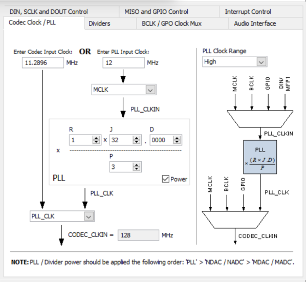
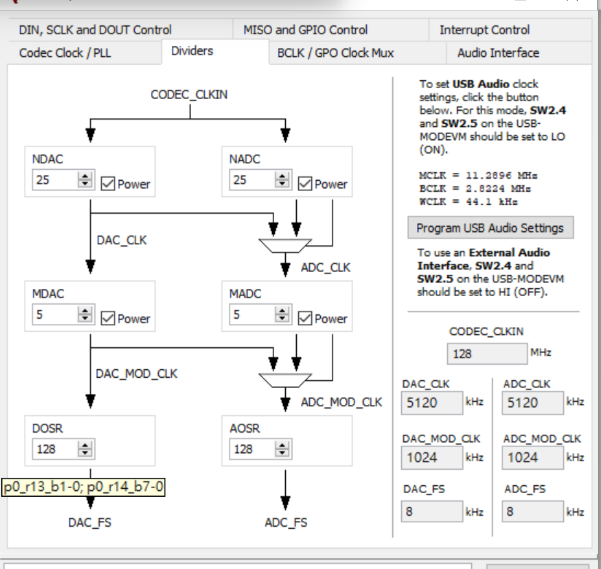
    The following we show the our PLL setting:

    AudioCodec_pageSelect(TI3254_PAGE_0);
    AudioCodec_regWrite(TI3254_AUDIO_IF_1_REG, 0x0C);
    
    AudioCodec_pageSelect(TI3254_PAGE_0);
    AudioCodec_regWrite(TI3254_CLK_MUX_REG, 0x03);       // PLL Clock is CODEC_CLKIN
    AudioCodec_regWrite(TI3254_CLK_PLL_P_R_REG, 0x80 | 0x30 | 0x01);    // PLL is powered up, P=3, R=1
    AudioCodec_regWrite(TI3254_CLK_PLL_J_REG, 0x020);     // J=32
    AudioCodec_regWrite(TI3254_CLK_PLL_D_MSB_REG, 0x00); // D = 0000
    AudioCodec_regWrite(TI3254_CLK_PLL_D_LSB_REG, 0x00); // D = 0000
    
    AudioCodec_regWrite(TI3254_CLK_NDAC_REG, 0x80 | 0x19);      // NDAC divider powered up, NDAC = 25
    AudioCodec_regWrite(TI3254_CLK_MDAC_REG, 0x80 | 0x05);      // MDAC divider powered up, MDAC = 5
    AudioCodec_regWrite(TI3254_DAC_OSR_MSB_REG, 0x00);   // DOSR = 0x0180 = 128
    AudioCodec_regWrite(TI3254_DAC_OSR_LSB_REG, 0x80);   // DOSR = 0x0180 = 128
    
    AudioCodec_regWrite(TI3254_CLK_NADC_REG, 0x80 | 0x19);      // NADC divider powered up, NADC = 25
    AudioCodec_regWrite(TI3254_CLK_MADC_REG, 0x80 | 0x05);      // MADC divider powered up, MADC = 5
    AudioCodec_regWrite(TI3254_ADC_OSR_REG, 0x80);       // AOSR = 128 
    
    AudioCodec_regWrite(TI3254_BCLK_N_DIV, 0x80 | 0xa); // 5120 / 10 = 512 
    AudioCodec_regWrite(TI3254_AUDIO_IF_3_REG, 0x04);

    BR

    Trevor

  • Hi Trevor,

    I don't think you have selected the right settings in the clock divider GUI.

    For 8 kHz the EVM uses a different MCLK frequency. You are probably setting the PLL input frequency as 11.29 MHz.

    That is the most likely reason for the discrepancy.

    Best Regards.

  • Hi Trevor,

    I think it will be easier for me to understand what is going on if you can just share the register dump of Page 0 and Page 1 while the codec is running.

    Please also share the frequencies of all the input clocks to the codec.

    I shall examine it and respond to you.

    Best Regards.

  • Hi Diljith,

    Regarding clock divider GUI, we just use this GUI to calculate PLL setting for  "CC3200AUDBOOST". We don't modify the clock divider GUI, do we need to modify the clock divider GUI for EVM?

    BR

    Trevor

  • Hi Diljith,

    Regarding EVM:

    MCLK = 4.096MHz, WCLK = 8KHz  BCLK = 512KHz.

    555TI_PAGE_0_REGISTERS.xls

    555TI_PAGE_1_REGISTERS.xls

    BR

    Trevor

  • Hi Diljith,

    As mentioned earlier, we flash the "USBMODEVMxxxx_8KHZ.BIN" firmware into AIC3254 EVM. Although we can' t use AIC3254 CS to get correct register status from "REGISTER TABLE", but we found the script of "USBMODEVMxxxx_8KHZ.BIN" firmware. please refer to attached file.

    Regarding this script,

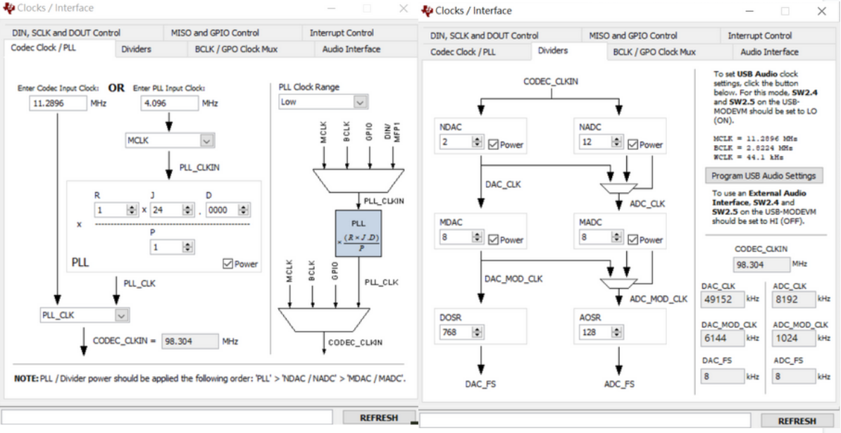
    MCLK = 4.096MHz, BLCK = 512KHz, WCLK =8KHz,  P=1, R=1, J=24, D=0000 , NDAC = 2, MDAC = 8 , DOSR = 768 ,NADC = 12, MADC = 8 AOSR = 128

    Note : About NADC, the comment seems be wrong.

    ###############################################
    # Clock and Interface Settings
    # ---------------------------------------------
    # The codec receives: MCLK = 4.096 MHz,
    # BLCK = 512 kHz, WCLK = 8 kHz
    ###############################################
    #
    # Select Page 0
    w 30 00 00
    #
    # PLL_clkin = MCLK, codec_clkin = PLL_CLK,
    # PLL on, P=1, R=1, J=24, D=0000
    w 30 04 03 91 18 00 00
    #
    # NDAC = 2, MDAC = 8, dividers powered on
    w 30 0b 82 88
    #
    # DOSR = 768
    w 30 0D 03 00
    #
    # NADC = 2, MADC = 8, dividers powered on
    w 30 12 8C 88
    #
    # AOSR = 128
    w 30 14 80
    #
    ###############################################


    We refer to this script and apply this configuration into "CC3200AUDBOOST", because CC26x2 can't generate the 4.096MHz clock, so we use the AIC3254 EVM's MCLK connect to CC3200AUDBOOST and configure CC3200AUDBOOST to I2S master mode. Here are the changes we showed:

    AudioCodec_regWrite(TI3254_AUDIO_IF_1_REG, 0x0C); //AIC3254 as Master
    
    //BCLK Divider value = 60
    AudioCodec_regWrite(TI3254_BCLK_N_DIV, 0x80 | 0x3C);
    AudioCodec_regWrite(TI3254_AUDIO_IF_3_REG, 0x04);

    Currently, we can get the same result(out of band frequency ) with AIC3254 EVM. We also measured the clock waveforms for two boards:

    For AIC3254 EVM : MCLK = 4.096MHz, BLCK = 512KHz, WCLK =8KHz

    For CC3200AUDBOOST : MCLK = 4.096MHz, BLCK = 819KHz, WCLK =8KHz

    Our questions are :

    1. We input the PLL setting of script to clock divider GUI, please see the following figure, do you know  why BCLK is 512KHz?

    2. About CC3200AUDBOOST, if we don't add the following two line, we can't get the same result with EVM?

    AudioCodec_regWrite(TI3254_BCLK_N_DIV, 0x80 | 0x3C);
    AudioCodec_regWrite(TI3254_AUDIO_IF_3_REG, 0x04);


    ###############################################
    #
    # For use with the following firmware image:
    # ..\image\USBMODEVM0200_8KHZ.BIN
    #
    # This script configures both ADC and DAC
    # channels for line-in and headphone
    # monitoring.
    #
    # An analog loopback test can be performed by
    # connecting a 1/8" male to male cable from
    # J10 (Headphone Test) to J1 (IN1).
    #
    ###############################################


    ###############################################
    # Software Reset
    ###############################################
    #
    # Select Page 0
    w 30 00 00
    #
    # Initialize the device through software reset
    w 30 01 01
    #
    ###############################################


    ###############################################
    # Clock and Interface Settings
    # ---------------------------------------------
    # The codec receives: MCLK = 4.096 MHz,
    # BLCK = 512 kHz, WCLK = 8 kHz
    ###############################################
    #
    # Select Page 0
    w 30 00 00
    #
    # PLL_clkin = MCLK, codec_clkin = PLL_CLK,
    # PLL on, P=1, R=1, J=24, D=0000
    w 30 04 03 91 18 00 00
    #
    # NDAC = 2, MDAC = 8, dividers powered on
    w 30 0b 82 88
    #
    # DOSR = 768
    w 30 0D 03 00
    #
    # NADC = 2, MADC = 8, dividers powered on
    w 30 12 8C 88
    #
    # AOSR = 128
    w 30 14 80
    #
    ###############################################


    ###############################################
    # Configure Power Supplies
    ###############################################
    #
    # Select Page 1
    w 30 00 01
    #
    # Disable weak AVDD in presence of external
    # AVDD supply
    w 30 01 08
    #
    # Enable Master Analog Power Control
    w 30 02 00
    #
    # Set the input power-up time to 3.1ms (for ADC)
    w 30 47 32
    #
    # Set the REF charging time to 40ms
    w 30 7b 01
    #
    ###############################################


    ###############################################
    # Configure Processing Blocks
    ###############################################
    #
    # Select Page 0
    w 30 00 00
    #
    # PRB_P2 and PRB_R2 selected
    w 30 3C 02 02
    #
    ###############################################


    ###############################################
    # Configure ADC Channel
    ###############################################
    #
    # Select Page 1
    w 30 00 01
    #
    # Route IN1L to LEFT_P with 20K input impedance
    w 30 34 80
    #
    # Route CM1L to LEFT_M with 20K input impedance
    w 30 36 80
    #
    # Route IN1R to RIGHT_P with 20K input impedance
    w 30 37 80
    #
    # Route CM1R to RIGHT_M with 20K input impedance
    w 30 39 80
    #
    # Unmute Left MICPGA, Gain selection of 6dB to
    # make channel gain 0dB, since 20K input
    # impedance is used single ended
    w 30 3b 0c
    #
    # Unmute Right MICPGA, Gain selection of 6dB to
    # make channel gain 0dB, since 20K input
    # impedance is used single ended
    w 30 3c 0c
    #
    # Select Page 0
    w 30 00 00
    #
    # Power up LADC/RADC
    w 30 51 c0
    #
    # Unmute LADC/RADC
    w 30 52 00
    #
    ###############################################


    ###############################################
    # Configure DAC Channel
    ###############################################
    #
    # Select Page 1
    w 30 00 01
    #
    # De-pop: 5 time constants, 6k resistance
    w 30 14 25
    #
    # Route LDAC/RDAC to HPL/HPR
    w 30 0c 08 08
    #
    # Power up HPL/HPR
    w 30 09 30
    #
    # Unmute HPL/HPR driver, 0dB Gain
    w 30 10 00 00
    #
    # Select Page 0
    w 30 00 00
    #
    # DAC => 0dB
    w 30 41 00 00
    #
    # Power up LDAC/RDAC
    w 30 3f d6
    #
    # Unmute LDAC/RDAC
    w 30 40 00
    #
    ###############################################

    Thanks.

    BR

    Trevor

  • Hi Diljith,

    We found that the root cause of out of band noise is related to DOSR, if DOSR = 768 , there is no out of band noise.

    What is your comment on the test results?

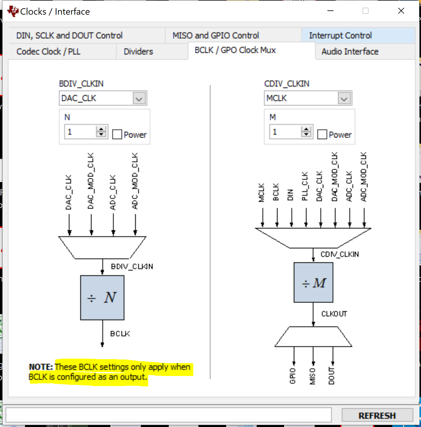
    Currently, the CC3200AUDBOOS' s BCLK  is 819KHz(Regarding "BDIV_CLKIN Multiplexer Control", we configure BDIV_CLKIN = DAC_CLK, so BCLK = 49152KHz / 60 = 819.2KHz ) 

    Do you have any recommend divider value?

    Thanks.

    BR

    Trevor

  • Hi Diljith,

    Update some information related to DOSR = 768, it seems what the DSOR needs to be set to 768 to achieve high performance.

    Thanks.

    BR

    Trevor

  • Hi Diljith,

    Do you have any update?

    BR

    Trevor

  • DOSR is set to 768 in the default PPS settings. That gives the best performance. So yes, please keep DOSR at 768. 

    I did not quite follow your question on the BCLK divider. For 8 kHz operation how can you get a 819 kHz BCLK. Shouldn't there be an integer ratio between the BCLK and FS.

    Best Regards.

  • Hi Diljith,

    We input the EVM PLL setting into AIC3254 CS clock divider GUI, please refer to the following figure, you could see the DAC_FS & ADC_FS are 8KHz.

    Because we configure the CC3200AUDBOOS as I2S master mode(EVM is slave mode). so we need to configure the BCLK.

    Regarding the clock divider GUI, the DAC_CLK = 49152KHz, we don't know how much speed BCLK is needed. we just tried to use  the 60 divider value,  

    Do we need to follow the EVM (BCLK=512KHz)? If yes, we could set the divider value to 96(49152 / 96 = 512).

    BR

    Trevor

  • No, there is no need to configure BCLK if CC3200AUDBOOS is bus master.

    BCLK settings (BCLK/GPO Clock Mux Tab) is required only when BCLK is an output. The other dividers (NADC, MADC, NDAC, MDAC, AOSR, DOSR, P,R,J,D) are all required and what you have shown appears to be proper.

    BR.

  • Hi Diljith,

    Currently,  the CC3200AUDBOOS’ BCLK is configured to output.

    So we can measure 819 kHz on BCLK pin.

    BR

    Trevor

  • Generally BCLK and FS are derived from a common clock source by integer divisions. So I am a little surprised to hear a combination of 819 kHz BCLK and 8 kHz WCLK. It will be good to check it with a simultaneous capture of both signals. Aren't there an integer number of BCLK periods with one period of WCLK?

    Best Regards.

  • Hi Diljith,

    If you have any concerns, we can set the divider value  to 96(49152 / 96 = 512).

    We can measure the BCLK & WCLK frequency, but it is difficult to check that an integer number of BCLK periods with one period of WCLK. Do you have others way to check it?

    BR

    Trevor

  • Hi Trevor,

    The BCLK divider has to be programmed only if BCLK is an output from AIC3254. If you want to set BCLK as output then you can set it to 96 to get 512 kHz clock frequency.

    There is no need to program the divider if BCLK is input (i.e. CC3200AUDBOOS's BCLK is output). Leave it at default.

    Do you think there is an error in the measurement of BCLK frequency? I expect to see the BCLK frequency to be an integer multiple of WCLK. If not please check with the processor team.

    Best Regards.