This thread has been locked.

If you have a related question, please click the "Ask a related question" button in the top right corner. The newly created question will be automatically linked to this question.

TLV320ADC3140: Changing sampling frequency

Part Number: TLV320ADC3140

Hello team,

In my use case, the sampling frequency fs for TLV320ADC3140 is variable. So, could you please help me to check a couple of points for this use case?

  1. I assume I need to update the fs by the procedure below. Could you check if the procedure should be correct?
    1. Change fs (fs= 8, 11.025, 16, 22.05, 24, 32, 44.1, 48 kHz)
    2. Host changes MCLK for audio ADC input (MCLK = 256 * fs (e.g. when fs=24kHz, MCLK will be 6.144MHz))
    3. Host updates the register (target registers are CLKGEN_CFG1 and CLKGEN_CFG4)  
    4. The ADC generates BCLK (=32fs) and FSYNC(=fs) from the MCLK. The ADC sends the data, MCLK and FSYNC to the host.

  2. Could you please advise how to generate my target BCLK, FSYNC for fs=8kHz, 22.05kHz, 44.1kHz?
    1. In case MCLK=2.048MHz : FSYNC=8kHz, BCLK = 256kHz. BCLK_DIV will exceed 256 so it's unconfigurable
    2. In case MCLK=5.6448MHz : FSYNC=44.1kHz, BCLK = 705.6kHz. BCLK_DIV needs to be 104.5 so it's unconfigurable
    3. In case MCLK=11.2896MHz : FSYNC=44.1kHz, BCLK = 1411.2kHz. BCLK_DIV needs to be 52.25 so it's unconfigurable

    However, I found some alternative setting with the EVM and GUI. For instance, when the fs=16kHz, you will see
    MCLK=4.096HMz : FSYNK=16kHz, BCLK=512kHz.
    By keeping PLL setting but changing MCLK to 2.048MHz, it can output my target FSYNC=8kHz and BCLK=256kHz.
    The similar procedure is applicable for the 22.05kHz and 44.1kHz case. 
    From the above, I'd like to apply PLL setting for fs=16kHz when fs=8kHz.
    Similarly, I'd like to apply PLL setting for fs=32kHz when fs=22.05kHz and 44.1kHz.
    Do you think this should be OK?

  3. Do you recommend to mute the output when switching fs? Do you have any other recommendation when switching fs?

Best regards,

Itoh

  • Hi Itoh-san,

    Thank you for your question. Many of our engineers are taking vacation due to the Christmas holiday in the US. Once they return from the holiday, they will address your question. I apologize for any inconvenience this causes. 

  • Hi Itoh-san,

    The Application Note - Configuring and Operating TLV320ADCx140 as Audio Bus Master (www.ti.com/.../sbaa382)  - lists the options available for Master-mode configuration.

    There are two registers for master mode configuration - MST_CFG0 and MST_CFG1.

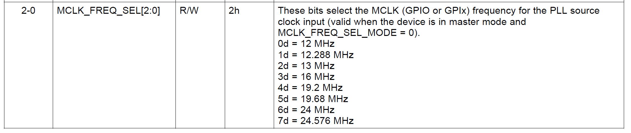
    In MST_CFG0, the master clock frequency has to be specified.

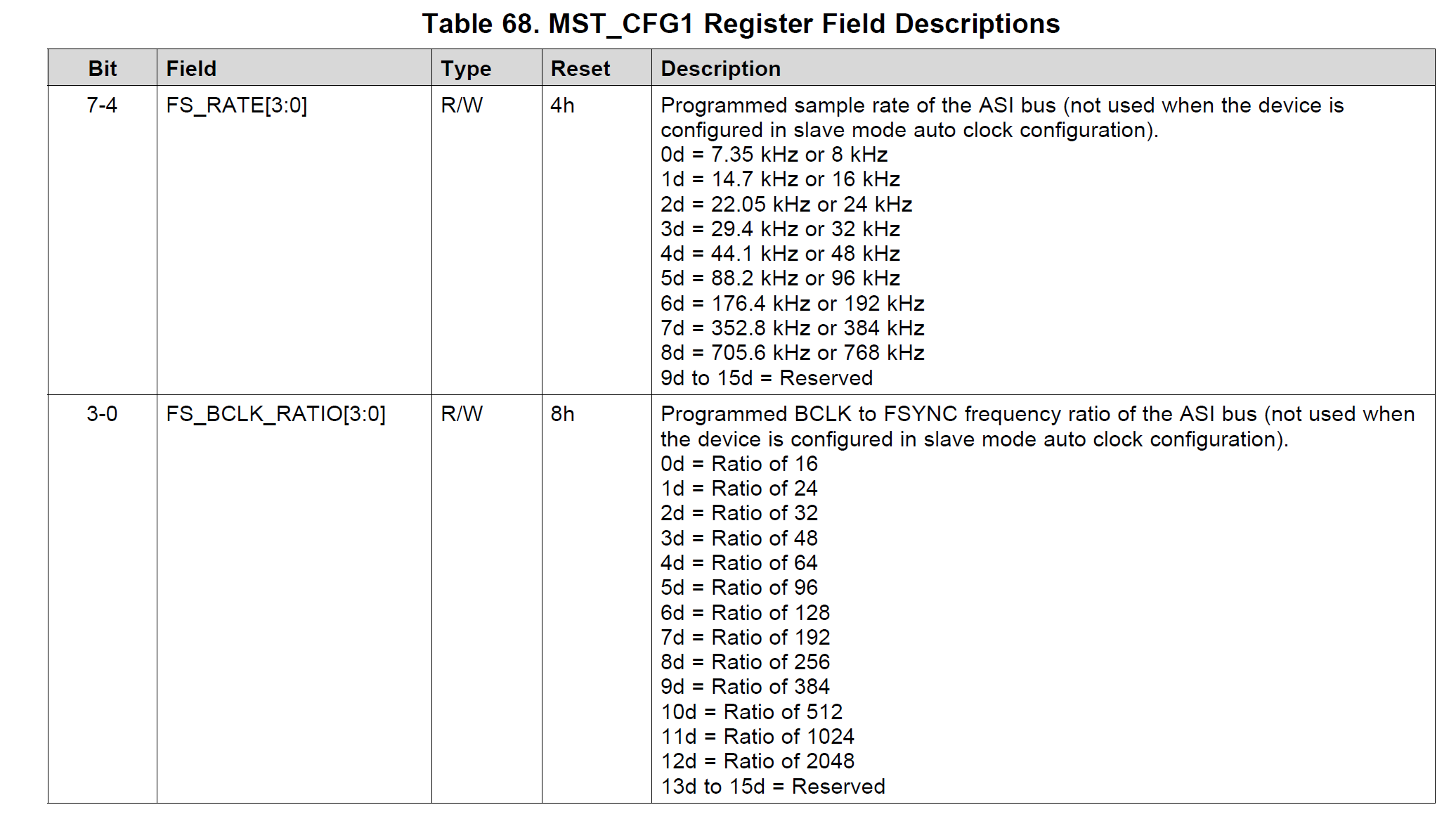
    In MST_CFG1, the FS_RATE and FS_BCLK_RATIO have to be specified.

    Depending on your system, these three registers have to be set appropriately.

    The supported Master-clock frequencies are:

    The supported BCLK and FS values are

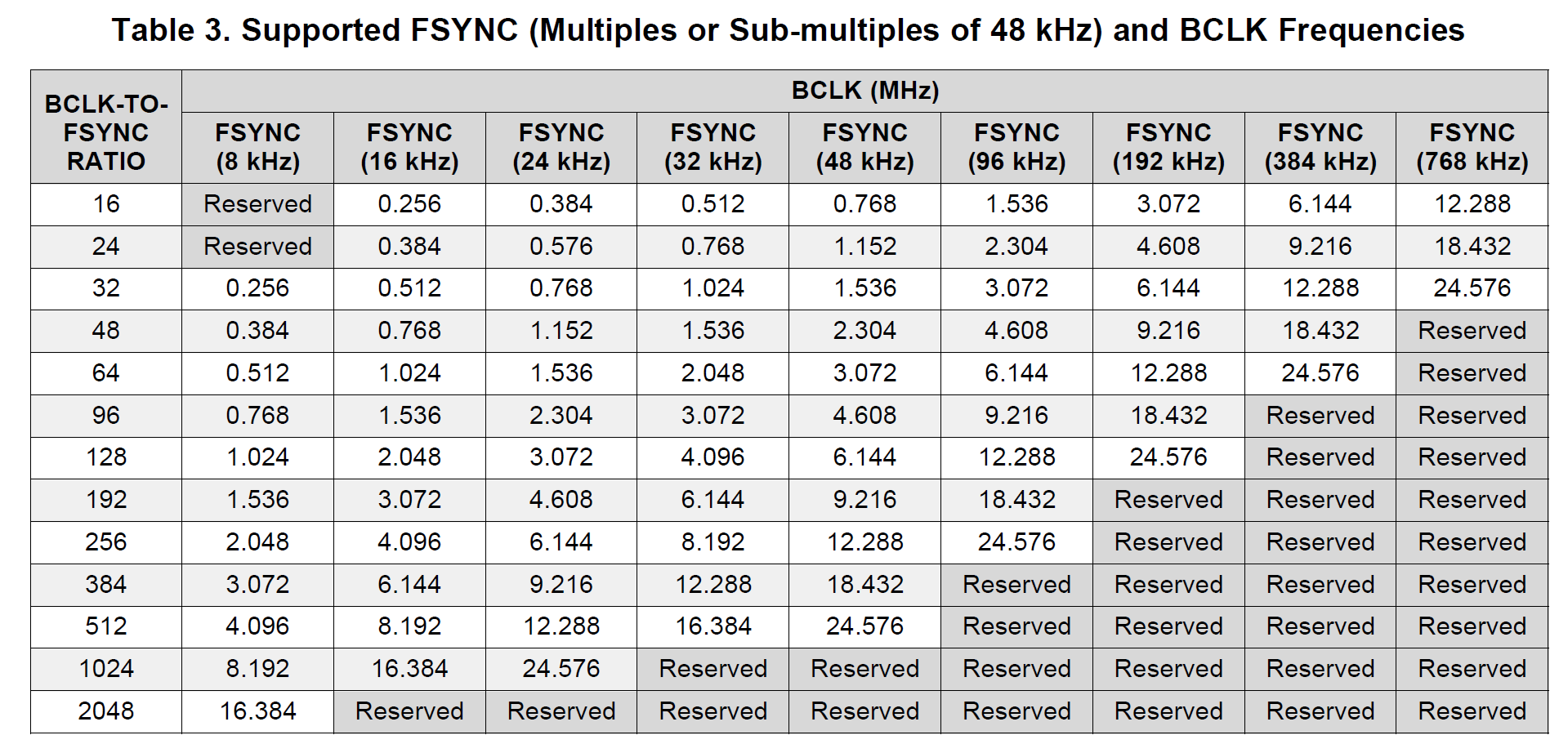
    For multiples and sub-multiples of 48 kHz the following BCLK and FS are supported.

    Section 2.1.1.1 has a second table for 44.1 kHz multiples and sub-multiples.

    All the options listed above are for auto-mode clock configuration. If the clock that you are using is not supported in auto mode, we can always configure the clock-tree in manual mode. We can help you with that.

    Changing sample-rate would required you to power-down the ADC, reconfigure the clocks and then power-up again.

    I do not think we support a run-time update of the clock-rate, so muting will not be sufficient.

    Let me know if you have further questions.

    Best Regards.

  • Hello Diljith-san,

    Thank you so much for your support.

    You mentioned changing sample-rate would required you to power-down the ADC, reconfigure the clocks and then power-up again.

    So, do you mean it requires hardware shutdown and then need to go to sleep mode and then active mode as described in 8.4.1-8.4.3?

    Also, let me ask you one additional question.

    In my use case, only channel 1 is used. I know unused input channels should be left floating from this thread.
    Do you recommend any register setting change for the use case with unused channels? 

    Regards,
    Itoh

  • Hi Itoh-san,

    No need for hardware shutdown. Just power-down the ADC by writing to PWR_CFG Register (page = 0x00, address = 0x75) register. Then update the clock configuration registers and power it back again by writing to PWR_CFG Register (page = 0x00, address = 0x75) register.

    Unused inputs can be left floating or ac-coupled to ground (preferred). Disable the unused channel in IN_CH_EN Register (page = 0x00, address = 0x73) and ASI_OUT_CH_EN Register (page = 0x00, address = 0x74) respectively.

    Best Regards.