Hi,
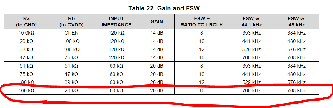
for TAS5766M, I implemented Ra and Rb so that the PWM frequency is 768kHz, but the actual output PWM frequency is 384kHz.
Two of the six prototypes have this symptom.
What are the possible mistakes?
Hi,
for TAS5766M, I implemented Ra and Rb so that the PWM frequency is 768kHz, but the actual output PWM frequency is 384kHz.
Two of the six prototypes have this symptom.
What are the possible mistakes?