Other Parts Discussed in Thread: INA1620, , BUF634A, OPA210, BUF634, NE5534
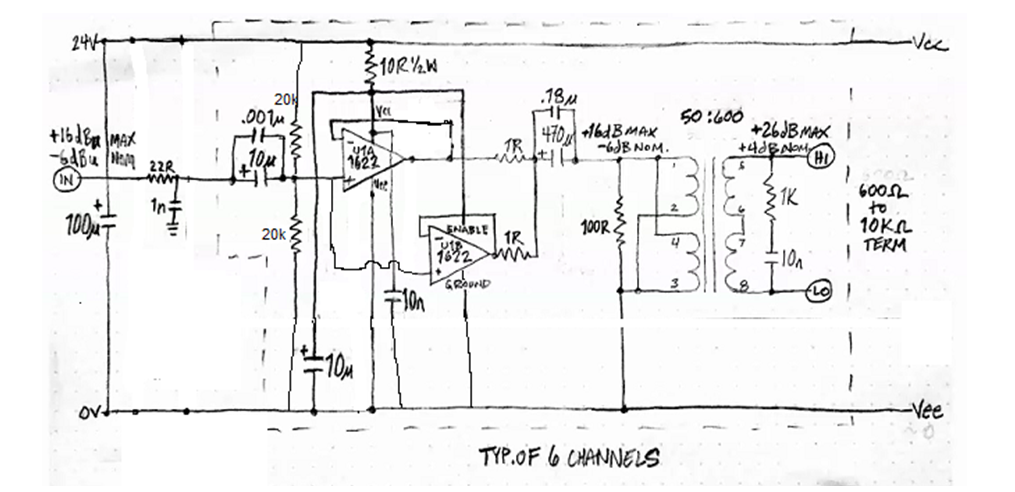
I'm thinking of using the OPA1622 as a parallel buffer to drive a line output transformer with a 33Ω-100Ω primary impedance and a 10dBu step up. Power is 24V single. One little PCB would do six of these outputs, and there would be six PCBs in the system. I've combined the parallel buffer from the INA1620 application note with the midsupply reference application drawing on the BUF634A data sheet. There is one BUF634A and six OPA1622s on each PCB. I doubt the semiconductor aspect of this design needs to exceed 80kHz flat bandwidth.
Some mysteries and possible adjustments below...any thoughts welcome!
- I'm unsure about smoothing/bypass cap values for this sort of load.
- Are there any supporting components I'm missing?
- With that 10K bias resistor, I can't tell if either half of the OPA1622 requires a resistor (or RC pair) in its feedback loop. Transients can be unpredictable (unsure if they would be more than 10mA), and I don't fully understand what happens at powerup when the amp is used as a unity gain buffer with a low or nonexistant source resistance.
- I'm unsure whether the ground pin ties to midsupply or 0V. I think midsupply, drawn as such.
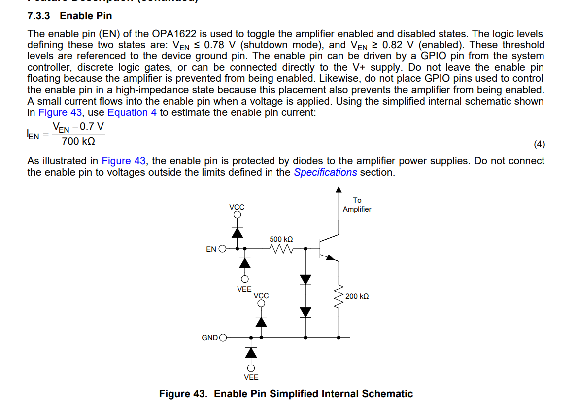
- How large of a startup transient will be produced if the enable pin is simply tied to Vcc, rather than getting 22K to Vcc and 10K to ground (or midsupply here)? The data sheet talks about it being noticeable on headphones.
- While the BUF634A is an easy choice to buffer the mid-supply reference, I'm unsure if it's overkill -- maybe an OPA210 or similar would suffice? How much does offset matter here? The BUF634A has a large offset IIRC.
Thanks for taking a look.
![]()