This thread has been locked.

If you have a related question, please click the "Ask a related question" button in the top right corner. The newly created question will be automatically linked to this question.

PCM1690: Pop noise after releasing reset

Part Number: PCM1690

Hi,

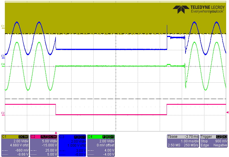
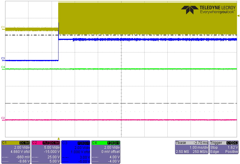
My customer is evaluating the PCM1690 with DC-coupled(referring to figure 40 on the datasheet).

Pop noise can be heard during biasing DC voltage of outputs after releasing RST.

Is there any solution to solve pop noise?

Best Regards,

Kuramochi

  • Hi Kuramochi-san,

    I am not aware of a this pop noise behavior.  Can you confirm the following:

    1. What digital clock signals are present during this event?

    2. Are the power supplies at their final voltage when reset is released? (5V and 3.3V)

    3. Can they use an oscilloscope to capture the behavior?

    Thanks,

    Paul

  • Hi Paul-san,

    >1. What digital clock signals are present during this event?

    LRCLK and BCK/SCKL

    2. Are the power supplies at their final voltage when reset is released? (5V and 3.3V)

    Yes.

    3. Can they use an oscilloscope to capture the behavior?

    Please see the attached file.

    The inside red rectangle is a pop noise waveform.

    PCM1690.xlsx

    Best Regards,

    Kuramochi

  • Hi Paul-san,

    How is this situation?

    Best Regards,

    Kuramochi

  • Hi Paul-san,

    How is this situation?

    Best Regards,

    Kuramochi

  • Hi Kuramochi-san,

    Sorry for the delay.  I am confused at the voltage scale of the scope shots you shared.  Is the red line being gained up by some other stage? Is the scope calculating this line, or is the output of the differential-to-single-ended amplifier stage?  Does the glitch change if DIN = 0 during the reset event? Is it possible to mask the SCK signal with the digital RST input?

    Thanks,

    Paul

  • Paul-san,

    Thank you for your reply.

    >  Is the red line being gained up by some other stage?

    > Is the scope calculating this line, or is the output of the differential-to-single-ended amplifier stage?

    The red line is calculated by the oscilloscope.

    The yellow line and the blue lines are monitored directly.

    >Does the glitch change if DIN = 0 during the reset event?

    I'll check it.

    >Is it possible to mask the SCK signal with the digital RST input?

    What does "mask" mean?

    When should we input digital RST?

    Best Regards,

    Kuramochi

  • Hi Paul-san,

    >Does the glitch change if DIN = 0 during the reset event?

    Though my customer tried this, the glitch was not varied.

    Best Regards,

    Kuramochi

  • Paul-san,

    How is this situation?

    Best Regards,

    Kuramochi

  • Hi Kuramochi-san,

    I have confirmed this behavior, when RST is released and SCK/BCK/LRCK is applied, you can see these transients.

    During my testing, I found that if I2S signals were applied, or just SCK, there was no transient.  I recommend that if the customer us using the RST signal, they disable the I2S clocks.  The could "mask" the LRCK and BCK with RST by doing a logic AND function with the RST signal.

    Thanks,
    Paul

  • Hi Paul-san,

    Thank you for your help.

    > I recommend that if the customer is using the RST signal, they disable the I2S clocks.

    Does it mean that the transient can be avoided by what I2S signals are inputted after the RST signal?

    Best Regards,

    Kuramochi

  • Hi Kuramochi-san,

    yes, I did not find transients if the I2S input signals were disabled.

    Thanks,

    paul

  • Hi Paul-san,

    Though my customer input I2S signal after RST signal, the transient is occured.

    Could you share the waveform that you tested?

    Best Regards,

    Kuramochi

  • Here are two images:

    Yellow: SCK input

    Red: RST signal

    Blue: VOUT1+, totally unfiltered (except scope filtering)

    Green: VOUT post LPF, single-ended to differential amplifier,

    You can see the glitch in this image.

    Second image:

    Yellow: SCK input

    Red: RST signal

    Blue: VOUT1+, totally unfiltered (except scope filtering)

    Green: VOUT post LPF, single-ended to differential amplifier,

    Here you can see that the output is stable after exiting reset and all the I2S inputs are disabled.

    In the case where I2S data is applied after the reset is complete, it is still possible to see a glitch.  In the below image, all I2S inputs are resumed at the same time, and DIN is non-zero.

    One way to reduce this glitch is to enable SCK, but keep DIN connected to LOW.

  • Hi Paul-san,

    Thank you for your support.

    Pop noise occurs on my customer's board even if DIN is zero.

    It may be difference of dispersion by samples.

    And I found the following in the datasheet.

    Is this "pop noise" stand for the phenomenon in this time?

    If yes, I think that pop noise can not be avoided.

    Best Regards,

    Kuramochi

  • Hi Kuramochi-san,

    As you can see in my last image, there is still a small transient on the VOUTx+ line, but I found a similar transient on the VOUTx- line as well and I did not see any after the transient.  It is possible that in their system (or in some devices) this transient can still be heard.  

    It is possible that a pop noise cannot be avoided without external muting.  Does their amplifier stage features a SHUTDOWN or MUTE stage?