This thread has been locked.

If you have a related question, please click the "Ask a related question" button in the top right corner. The newly created question will be automatically linked to this question.

TS3A227E: Schematic Design

Part Number: TS3A227E


Hi All,

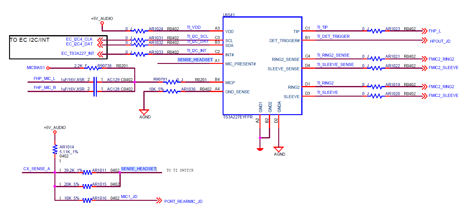
The audio part of our desktop using the CX20632 Codec+TS3A227EYFFR solution for design, and I have two questions on TS3A227E as follows:

1. I don't sure the design of MCP/GND_SENSE/MIC_PRESENT pin wrong? Can you help to review it?

2. Can we use the main control device to control TS3A227E force to switch to European and American standards  without reinserting during the production testing? 

Kind Regards,

Lumina

  • Hi Lumina,

    1. For the Review:

    • MICP - The only concern I have here is that typically we recommend the microphone amplifier signal comes in as one line into MICP - those two signals will not sum correctly and this could cause degradation of applications performance
    • GND_SENSE should be connected directly to the GND net of the CODEC as a reference point for the IC.
    • MIC_PRESENT: This is an Open Drain Output Pin - To Function Correctly a pull-up resistor should be used
    • Other I2C Lines: Pull Up Resistors to I2C VDD is recommended, if already included in System  there shouldn't be an issue
    • Everything Else Looks Okay

    2. Independent Control:

    Please see section 9.4.2 in the datasheet, included below:

    So the short answer is that yes you can change switch configuration - but autonomous switch detection will override any manual control - but for the purposes of testing it is possible to control the device via I2C.

    If you have any other questions please let me know!

    Best,

    Parker Dodson

  • Hi Parker,

    Thanks a lot. I will carefully check my design.

    Best Regards