This thread has been locked.

If you have a related question, please click the "Ask a related question" button in the top right corner. The newly created question will be automatically linked to this question.

TAS5722L: Recover from error mode

Part Number: TAS5722L


Hi all,

We are using the TAS5722 on our board together with ApolloLake SOC running Linux4.19 and ALSA. We observe very seldom cases when during sound playing the Linux gets reboot and after new start no sound played. Even resetting of ApolloLake does not help. Only power cycle helps but this is not acceptable in our application

Now I got this error case. What I see:

  • the I2S Signals are ok
  • the PowerControl Register contains 0xFD (IC is not in sleep and not in shutdown mode)
  • the FaultsConfigAndErrorStatus Register contains 0x08 (SAIF clock errors are present)
  • the FAULTZ pin has short low spikes: low for 10us every 350us

When I write in PowerControl Register the 0xFC into PowerControl Register then the FAULTZ goes high and when write the 0xFD then the FAULTZ has again these short low every 350us. The datasheet describes short low on FAULTZ only for shutdown mode. But this is obviously not our case:

How can we recover the IC from this mode?

Thanks,

Best Regards,

Sergey

  • PS. Screenshot not attached:

  • Hello Sergey,

    Can you provide waveforms of your I2S signals and the frequencies for these waveforms. Can you also provide the schematic of your system.

    Best regards,

    Luis

  • Hi Luis,

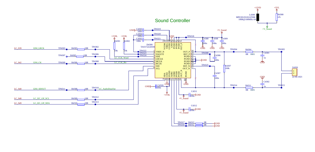
    Sure. Here is the part of schematic:


    and the waveforms from running system. Channel1 is LRCLK, channel2 is BCLK and channel3 is SDI. On last you see measured BCLK frequency is about 3,075MHz

    In my test case I am using device and one PCB. I made yesterday (when error occurred in PCB) the picture from system with channel1 BCLK and channel2 is FAULTZ. Other signals was also ok:

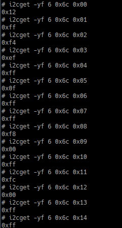
    The error happens very seldom. In test we are running each minute the reboot for Linux system. And this night error happened in device. I can only read out the register, can not check the signals. Here are the registers:

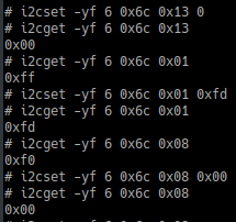
    I tried to set some register (0x13, 0x01, 0x08) to default values, but it did not help. The sound not playing after it:

    Hope it helps you. I will try to get the error in PCB again

    Thanks,

    Best Regards,

    Sergey

  • Hi Luis,
    I started my test for device and for PCB for weekend. PCB still works normally but device got the error. I read out the register from device. They have also same values as last week. Then for device:
        • I set all described in data sheet register with default values, it did not help
        • resetted ApolloLake SOC, it also did not help
        • Wrote in not documented register at address 0x07 the 0x00 value as it was in normally running PCB. The sound started (!)

    What this register at address 0x07 for?

    Thanks,
    Best Regards,
    Sergey

  • Hello Sergey,

    I'm looking into the 0x07 register. However i noticed you are violating some of the recommendations on our datasheet and using 100nF caps instead of 1uF decoupling caps for Vcom, Vreg, and GVDD. Should be unrelated but i would correct that to ensure device stability. Additionally, the BST caps are 100nF instead of 220nF which can cause issues with the device and should be corrected.

    Do you have a TAS5722LEVM, I would recommend trying to use the I2S signals from our EVM to see if you see the same issue after the cap changes.

    Best regards,

    Luis

  • Hi Luis,

    Thank you for information about wrong capacity values. I reported this case to HW development and they will adjust the capacities in next HW generation. But I also do not think, that this is the reason of current problem.

    I dont have the EVM under hand. But I got yesterday two additional PCBs for my tests. Now I have 3 PCBs and one device in test. In my test I run Linux reboot each minute. And this night 3 these test units got the error with codec. Interesting that in one on PCB the registers at addresses 0x13 and 0x14 have wrong values. When I wrote default value into 0x13 it started to play. And in 2 other PCBs was same case as yesterday: almost all register have strange values, when I wrote default in them it did not help, and when I wrote then the 0x00 into register at address 0x07 it started to play. I dont know why. Unfortunately something changed in yours Web site and I cant now attach a screenshot with how it was.

    But anyway, my idea now is: I see that the Linux kernel driver does not write the default values into registers at start, it starts the timer to poll the register at address 0x08 each 200ms and if driver recognizes the latching error in 0x08 then it wake ups the codec via writing values in register at address 0x01. Suspicion is: if the I2C transmittion interrupted in the middle due our reset for Linux system, then the codec goes in any error state what I see now. It will help to write the default values into registers at each driver start and write 0x00 into this 0x07 register. But this 0x07 register is not documented. I just suddenly found that it helps. It will be great if you can check what it for. And may be you have a better idea how to get the system running without this error.

    Thank you,

    Best Regards,

    Sergey

  • Hi Sergey,

    Thanks for your idea, our expert is working on your case and we will figure it out.

  • Hello Sergey,

    This register should not be related to this issue. If the amplifier is not properly powered up you can see this behavior of the FAULTZ pin has short low spikes: low for 10us every 350us. If the BST caps are incorrect like they are in the system it can cause the amplifier to not work properly and pull alot of current which may not allows the amplifier to properly power up.

    Could you measure the current draw of your voltage rails during this startup sequence where you see this error.

    Best regards,

    Luis

  • Hi Luis,

    >Could you measure the current draw of your voltage rails during this startup sequence where you see this error.

    I guess that it is almost impossible. The error ist very very seldom. Just to understand: we are powering the device only once. And in test case we are running Linux system reboot each minute (not the power cycle). In the test day before yesterday I started 5 such test units for whole night. And at the morning found that only one test unit got the error. For other test units worked fine


    >If the BST caps are incorrect like they are in the system it can cause the amplifier to not work properly and pull alot of current which may not allows the amplifier to properly power up.

    Ok, good idea. I will solder correct capacities in test units and will try it. But it will take several day. I inform you about results

    Thanks,

    Best Regards,

    Sergey

  • Hello Sergey,

    I will be awaiting the results from your tests.

    Best regards,

    Luis

  • Hi Luis,

    I got get the capacitors with correct values for checking of yours idea. But on the other side more than one week ago I implemented in Linux kernel driver setting of default registers values and writing 0 value into register at address 0x07 at the start. And after this I did not see the codec problem any more. I thing that my idea with interrupted I2C transmission and codec behaviour in this case was correct. I guess we can close this communication

    Thank you for great support,

    Best Regards,

    Sergey