This thread has been locked.

If you have a related question, please click the "Ask a related question" button in the top right corner. The newly created question will be automatically linked to this question.

TLV320AIC3109-Q1: Input data through mic to codec chips and do play, it always be a strong background noise.

Part Number: TLV320AIC3109-Q1


Hi

Input data through mic to codec chips and do play, it always be a strong background noise.

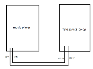
To do a comparative test, I used a mobile to play music, tansfered data to codec chips via the 3.5 headphone cable and do play.

The results shows that there is still a strong background noise, the sound is not clear.

The test environment is as follows:

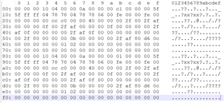
The register dump information is as follows:

Are there any good suggestions to help me investigate the problem?

Thank you very much!

Rofeo Chen(Chen Haofeng)
Automotive Business Group
Rosenberger Asia Pacific Electronic Co., Ltd.

  • Hi Rofeo,

    Looking through the register dump, I noticed that the ADC is overflowing. The overflow flag can be observed in register 11. An overflow indicates that the filters are experiencing overflow and can be due to digital clipping. Register 0x0F shows that there is 47.5dB applied to the PGA. Please lower this gain to see if the sound quality improves. The full scale input to the device is .707Vrms in Single-Ended and 1.414Vrms for differential. 

    Another thing I would like to point out is in the block diagram you sent over, it looks like the MIC input is differential. Is this the case? If so, Register 19 is configured for a single-ended input. Please change bit D7 to 1 if the input is a differential signal. 

    The inputs should also be AC coupled in order to be properly biased. In the block diagram, I do not see any AC coupling caps. Are the MIC1P and MIC1M inputs AC coupled?

    Regards,

    Aaron Estrada

  • hello Aaron


    I tried to set the value of register 0x0F to 0x10, and the sound quality improved. But there is still a strong background noise.

    The block diagram I gave may have misled you. The signal input is single-ended, not differential. The picture above is just to show my test environment.

    By consulting the chip manual, I see the following register description:


    I don’t know if I can try to set these registers to eliminate noise. If so, how do I set them?

  • Hello GuJin,

    There are programmable filters but I would first like to see if this noise is coming from an incorrect configuration. I have a couple of questions/comments:

    - Can you confirm what value of MCLK you are providing to the device? Based on the configuration, I would expect either 12.288MHz or 11.2896MHz. 

    - Is it possible to provide a full schematic? You can request to add me as a friend and you can share a schematic via private message if you wish.

    - What are the input signal conditions? Are you providing a .707Vrms, 1kHz sine wave? 

    - Is it possible to take an FFT?

    Regards,

    Aaron Estrada