Because of the holidays, TI E2E™ design support forum responses will be delayed from Dec. 25 through Jan. 2. Thank you for your patience.

This thread has been locked.

If you have a related question, please click the "Ask a related question" button in the top right corner. The newly created question will be automatically linked to this question.

TLV320AIC3120EVM-U: Using TLV320AIC3120EVM-U with an external MCU

Part Number: TLV320AIC3120EVM-U

Hello:

I am trying to use the TLV320AIC3120EVM-U with an external MCU. I got the I2C working and I am able to communicate on the I2C channel. However on the I2S, the MCU on board the dev board conflicts with my device - it seems the device in the dev board is driving the I2S lines, so my device cannot control them. 

Is there a way to disable the internal MCU to allow an external MCU to control the codec?

Thanks!

  • Hi Eduardo,

    Unfortunately, this EVM was designed to be a quick plug and play on a PC for easy evaluation and is not so straightforward when connecting an external MCU. If you wish to connect an external MCU for I2S, then you need to cut the traces connecting to the TAS1020b and use the test points for an external connection. 

    Regards,

    Aaron Estrada

  • Hi:

    Thanks Aaron, I agree after checking the schematics. I wanted to put how I dealt with it in case it is of use to anybody.

    We need to disconnect the I2S from the USB controller so we can use an external MCU. There is no need to disconnect the I2C- it will work as-is.

    To remove the I2S connection:

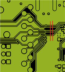
    Here is a picture of the top copper layer (top of board). To disconnect the codec from the USB controller, cut these traces with an x-acto knife. Two cuts makes sure you got it right!

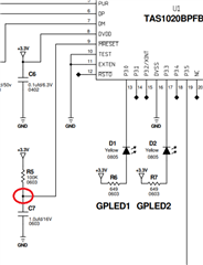
    Another detail is that on the MCLK net there is a clock generator. To disable it easily, jumper a wire from GND to the pad between R5 and C7

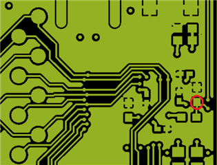
    On the top layer again, I did this jumper to the following pad:

    My experience was that even if you disabled the device, the I2S circuitry of the driver seemed to affect the system, so I still had to do the PCB cuts.

    I then proceeded to connect my external MCU signals to the test points for I2C,I2S.