This thread has been locked.

If you have a related question, please click the "Ask a related question" button in the top right corner. The newly created question will be automatically linked to this question.

LM4950: Bypass pin

Part Number: LM4950
Other Parts Discussed in Thread: TS5A22364

Hi

When BYPASS is high, VOUT is only at 12V and there is no sound output.
When the BYPASS is shorted to GND, sound is output instead. Please help to confirm what is the problem?

When the Bypass pin is pulled low, there is sound output, but the sound is abnormal and noisy

  1. Pin 1:0.2V AC, 2V DC inputBypass pin
  2. Pin 2, 8:5.6V DC
  3. Pin 9:0V AC, 6V DC input

  • Hello, 

    Our team is looking into this thread and will respond as soon as possible. 

    Best Regards, 

    Justin Beigel

  • Hi

    Are you forcing voltage/GND at bypass pin 8? This pin should be connected only to the correspondent decoupling capacitor.

    Bias for the device is set internally, and decoupled through pin 8. -VINB should not be connected to any external signal, and only use -VINA. Make sure to place series AC coupling capacitor and resistor at the input of -VINA, as shown in the data sheet. Please confirm you're using BTL connection at the output, similar to Figure 66 from data sheet.

    Best regards,
    -Ivan Salazar
    Applications Engineer - Low Power Audio & Actuators

  • Hi lvan

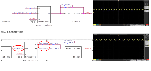
    The attachment is the customer's final schematics as follows
    LM4950 switches through TS5A22364
    Will ARIN R577 R575 10K, R519 R527 24.9K cause abnormal sound?

    New USB Audio (002) (2).pdf

  • Hi Gareth,

    The bypass seems to be pulled to some external voltage. Is there a chance customer can try to connect bypass pin only to decoupling capacitor? Perhaps removing the series resistors.

    Best regards,
    -Ivan Salazar
    Applications Engineer - Low Power Audio & Actuators

  • Hi Gareth,

    Is there any further feedback from customer?

    Best regards,
    -Ivan Salazar
    Applications Engineer - Low Power Audio & Actuators

  • Hi Ivan

    The customer changes the structure to the input/output terminal and adds capacitance and returns to normal

    What will the increase of capacitance affect?
    How much do I need to put in the capacitor?

  • Hi Gareth,

    Best practice in this case is to have the series coupling capacitors after the switch, not before it. This way the capacitors are blocking any offset that could couple from previous stage.
    The value of the coupling capacitors will affect frequency response as it forms a high-pass filter with series input resistors, something around 1uF should be OK.
    Is Cin2 affecting the result in the circuit at the bottom?

    Best regards,
    -Ivan Salazar
    Applications Engineer - Low Power Audio & Actuators