This thread has been locked.

If you have a related question, please click the "Ask a related question" button in the top right corner. The newly created question will be automatically linked to this question.

ADS8681: Intermittent errors in conversion values

Part Number: ADS8681
Other Parts Discussed in Thread: ADS8661, ADS8866, OPA320

I am using an ADS8681 ADC to capture 16-bit samples at a variable sampling rate up to 1MHz. It is being controlled by a Raspberry Pi Pico microcontroller using a single SPI channel, however there seems to be frequent intermittent errors in the captured conversion value. Please see the attached scope output for an example of this. This occurs regardless of the signal generator used, frequency/amplitude of the test signal or the sampling rate.

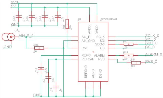
The original prototype board I built used an ADS8661 12-bit ADC instead, and this worked fine with no errors in the conversion values. I then made another board incorporating two separate channels of the same circuit (see attached schematic), but with the 12-bit ADS8661 swapped out for the 16-bit ADS8681. The new board worked as expected apart from these errors in the conversion values, which was present for both channels. I did not measure any excess noise in the power rails or SPI signal lines.

To see if this was due to a fault with the new board, I simply swapped out the ADS8661 on the old prototype board for the ADS8681, but found that this had caused the same errors to start appearing on this board. After swapping back to the 12-bit ADC, the errors were gone.

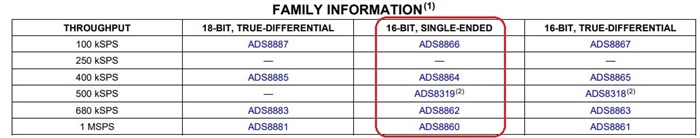
From what I can see in the respective datasheets for these ICs, there does not seem to be any functional difference (apart from the number of bits) between them when used at sampling frequencies < 1MHz. Is the assumption I have made here correct? or is the attached schematic unsuitable for use with ADS8681?

Any help with this issue would be greatly appreciated.

Luke

  • Hi Luke,

    Is there any amplifier used before the circuit your are showing? What's the purpose your are using 50ohm R31?

    Your timing shows you are applying a 10kHz(0.1ms cycle time) sinewave signal, ADS8681/ADS8661 has a 15kHz BW internal LPF, so your signal may be distorted. However, I need more information to figure out the reason to cause your waveform above.

    I would suggest:

    1. Apply a precision DC signal(e.g. 3V) to the ADC, share your raw data and timing capture with an oscilloscope for  SCLK,CONVST,SDI and SDO.

    2. Check sinewave signal with 1kHz frequency, share your raw data, also check your signal on AIN_P with an oscilloscope.

    Best regards,

    Dale

  • Hi Dale,

    Thanks for your reply.

    There is no amplifier used before the circuit and the 50ohm resistor is for impedance matching as the circuit is intended to be used as part of a 50ohm system. I have also tried removing this resistor, but it did not make any difference.

    1. I tried applying a 1V DC signal to the ADC with the ADC range set to +/- 2.5V. The glitches are still present, please see below for the conversion data. Unfortunately, I'm unable to capture the data signals (SCLK,CONVST,SDI,SDO) with the equipment I have available at the moment.

    [0xb30d, 0xb308, 0xb30c, 0xb312, 0xb305, 0xb32b, 0xb311, 0xb32a, 0xb307, 0xb321, 0xb30e, 0xb311, 0xb316, 0xb30e, 0xb31f, 0xb327, 0xb301, 0xb325, 0xb331, 0xb31a, 0xb311, 0xb319, 0xb300, 0xb309, 0xb2fa, 0xb311, 0xb322, 0xb304, 0xb309, 0xb311, 0xb316, 0xb30c, 0xb30b, 0xb317, 0xa0d, 0x1b3, 0x11b3, 0x16b3, 0xdb3, 0x9b3, 0x18b3, 0xffb3, 0x25b2, 0x17b3, 0xdb3, 0xb30a, 0xb308, 0xb301, 0xb311, 0xb320, 0xb300, 0xb31b, 0xb329, 0xb319, 0xb325, 0xb31c, 0xb327, 0xb31e, 0xb30f, 0xb311, 0xb311, 0xb311, 0xb319, 0xb319, 0xb309, 0xb305, 0xb329, 0xb30e, 0xb311, 0xb326, 0xb300, 0xb315, 0xb32d, 0xb30f, 0xb311, 0xb30d, 0xb319, 0xb311, 0xb311, 0xb31e, 0xb2f9, 0xb32c, 0xb331, 0xb334, 0xb32f, 0xb32c, 0xb31d, 0xb319, 0xb309, 0xb309, 0xb32f, 0xb332, 0xb31b, 0xb326, 0xb305, 0xb331, 0xb311, 0xb319, 0xb317, 0xb319, 0xb331, 0xb310, 0xb326, 0xb306, 0xb314, 0xb305, 0xb309, 0xb319, 0xb305, 0xb319, 0xb2fb, 0xb311, 0xb325, 0xb30f, 0xb319, 0xb326, 0xb306, 0xb325, 0xb319, 0xb310, 0xb321, 0xb2e8, 0xb2f8, 0xb300, 0xb307, 0xb309, 0xb2f5, 0xb30d, 0xb316, 0xb318, 0xb304, 0xb317, 0xb316, 0xb30d, 0xb317, 0xb323, 0xb2f5, 0xb305, 0xb310, 0xb2f9, 0xb319, 0xb316, 0xb2f9, 0xb318, 0xb2ff, 0xb310, 0xb311, 0xb303, 0xb31c, 0xa0d, 0xf9b3, 0x11b2, 0xf8b3, 0x18b2, 0x9b3, 0x9b3, 0x1fb3, 0x24b3, 0x2cb3, 0x5b3, 0x11b3, 0x18b3, 0x19b3, 0x9b3, 0xf9b3, 0x8b2, 0x6b3, 0xf9b3, 0x2eb2, 0x13b3, 0x11b3, 0x11b3, 0x31b3, 0xf9b3, 0x19b2, 0x17b3, 0x18b3, 0xf9b3, 0x9b2, 0x32b3, 0x9b3, 0x1fb3, 0x10b3, 0x11b3, 0x33b3, 0xfb3, 0x19b3, 0x32b3, 0x16b3, 0x19b3, 0x2fb3, 0x8b3, 0x25b3, 0xdb3, 0x19b3, 0x11b3, 0x2db3, 0x10b3, 0x26b3, 0x7b3]

    2. I've also provided the same capture data when a 1kHz 2Vp-p sine wave was applied. I checked the signal on AIN_P with a scope and it was as expected with no glitches.

    [0x943d, 0x917b, 0x8ea5, 0x8b87, 0x8870, 0x855a, 0x8251, 0x7f47, 0x7c31, 0x7935, 0x75fc, 0x72dd, 0x6fcf, 0x6cfa, 0x6a0f, 0x674a, 0x64a5, 0x6206, 0x5fa5, 0x5d43, 0x5b1f, 0x590e, 0x5701, 0x553e, 0x53ae, 0x523f, 0x50f2, 0x4fe5, 0x4efa, 0x4e53, 0x4dc0, 0x4da6, 0x4d7f, 0x4d74, 0x4dbd, 0x4e2d, 0x4eee, 0x4fba, 0x50c9, 0x5205, 0x5383, 0x5505, 0x56e5, 0x58ca, 0x5acd, 0x5cfd, 0x5f4d, 0x61c1, 0x645b, 0x66fa, 0x69db, 0x6ca0, 0x6f83, 0x7291, 0x75b6, 0x78d4, 0x7bde, 0x7efe, 0x8204, 0x8508, 0x8826, 0x8b4a, 0x8e4b, 0x9132, 0xa0d, 0xe694, 0x7e96, 0x3299, 0x959c, 0x79e, 0x11a1, 0x38a3, 0x30a5, 0xc6a7, 0x8aa8, 0xdaa, 0xac0a, 0xad54, 0xae82, 0xaf3c, 0xb01e, 0xb082, 0xb0da, 0xb0b9, 0xb0c8, 0xb081, 0xafd1, 0xaf4f, 0xae9a, 0xad6d, 0xac4b, 0xaad1, 0xa930, 0xa75e, 0xa54e, 0xa367, 0xa11f, 0x9ee6, 0x9c60, 0x99ef, 0x972a, 0x9467, 0x9189, 0x8eb4, 0x8b9c, 0x887c, 0x8555, 0x8259, 0x7f3e, 0x7c38, 0x7927, 0x75fe, 0x72d9, 0x6fcf, 0x6d01, 0x6a11, 0x6753, 0x64ab, 0x621f, 0x5fa7, 0x5d4d, 0x5b1b, 0x5929, 0x571e, 0x5552, 0x53b2, 0x523c, 0x50f1, 0x4fd5, 0x4ef9, 0x4e4e, 0x4dbb, 0x4daa, 0x4d7a, 0x4d82, 0x4db1, 0x4e47, 0x4ee0, 0x4fcd, 0x50b4, 0x520f, 0x5369, 0x550d, 0x56e3, 0x58de, 0x5adc, 0x5d00, 0x5f55, 0x61c0, 0x6452, 0x67e2, 0x6ab1, 0x6d7d, 0x7069, 0x7373, 0x76a0, 0x79b5, 0x7cc3, 0x7fd6, 0x82e3, 0x85ea, 0x8924, 0x8c42, 0x8f38, 0x920b, 0x94fe, 0x97be, 0x9a54, 0x9cf8, 0x9f4e, 0xa1a9, 0xa3c8, 0xa59a, 0xa79a, 0xa984, 0xab13, 0xac4a, 0xadb6, 0xaec7, 0xaf74, 0xb059, 0xb0b1, 0xb0b2, 0xb0df, 0xb0ce, 0xb065, 0xaff3, 0xaf28, 0xadf9, 0xad15, 0xabc9, 0xaa62, 0xa8a0, 0xa6d3, 0xa4c1, 0xa2b7, 0xa090, 0x9e10, 0x9bab, 0x9912]

    3. I did not realise the BW of the internal anti-aliasing filter was only 15kHz. I think I assumed it would be greater as the ADC is capable of sampling up to 1Msps. Is there any way to configure the ADC to bypass the filter? If not, could you recommend a similar IC that would allow capture of signals up to 100kHz?

    Luke

  • Hi Luke,

    Both ADS8661 and ADS8681 definitely should work for analog DC input or 1KHz sinewave signal. The glitch you observed was caused by something else in your system. When you check glitch on the analog input, make sure you have proper settings on the scope, otherwise you will not be able to capture the glitch.

    I have few questions if you still want to solve your problem on ADS8661 circuit:

    1. Are you using blue wires between ADC and your Raspberry Pi Pico microcontroller? 
    2. Are you using a solid ground plane for the ADC circuit?
    3. Did you monitor the REFIO and REFCAP to see if the voltage on both are 4.096V?

    No way to bypass the internal LPF on ADS8661. You may have to consider a solution of op-amp(e.g. OPA320)+ADS8866 ADC family below:

    Best regards

    Dale