This thread has been locked.

If you have a related question, please click the "Ask a related question" button in the top right corner. The newly created question will be automatically linked to this question.

ADS1231: SPI Interface w/ MSP430F5529

Part Number: ADS1231
Other Parts Discussed in Thread: MSP430F5529,

Hello,

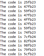
I'm using the following code to communicate between an ADS1231 and MSP430F5529 in my weight scale design. The resulting data is shown below. As you can see, the last two bytes of each data point are consistent as intended, but the first byte varies. What is the reason for this inconsistency? Does the SPI protocol have a problem with the first byte of transmission? Any help is very appreciated.

/*
 * main.c
 *
 * Updated on: Oct 22, 2020
 *     Author: Yamen Alimam
 */

#include <msp430.h> 
#include <stdint.h>
#include <stdio.h>

int main(void)
{
    WDTCTL = WDTPW | WDTHOLD;                              // hold watchdog timer

    UCB0CTL1 |= UCSWRST;                                   // software reset enable

    P3SEL = BIT1 + BIT2;                                   // configure SPI pins (P3.1 = MISO, P3.2 = SCLK)
    P2DIR |= BIT2 + BIT3;                                  // P2.2 = SPEED, P2.3 = PWDN, outputs
    P2OUT = 0x08;                                          // 10 SPS, active

    UCB0CTL0  = UCMST + UCSYNC + UCMODE_0 + UCMSB;         // master mode, msb first, synchronous
    UCB0CTL1 |= UCSSEL_3;                                  // select SMCLK (1 MHz)
    UCB0CTL1 &= ~UCSWRST;                                  // initialize SPI interface

    int32_t data1, code;
    int16_t data2;
    int8_t data3;

    while (1)
    {
        if((P1IN & 0x08) == 0)
        {
            while (!(UCB0IFG & UCTXIFG));
            UCB0TXBUF = 0x21;
            while (!(UCRXIFG));              // if RX operation is not complete, continue
            data1 = UCB0RXBUF;

            while (!(UCB0IFG & UCTXIFG));
            UCB0TXBUF = 0x22;
            while (!(UCRXIFG));
            data2 = UCB0RXBUF;

            while (!(UCB0IFG & UCTXIFG));
            UCB0TXBUF = 0x23;
            while (!(UCRXIFG));
            data3 = UCB0RXBUF;

            code = (data1 << 16) + (data2 << 8) + data3 + 0x800000;
            code &= 0x00ffffff;
            printf("The code is %lx\n", code);
        }
    }
}

  • Hi Yamen,

    I don't see a pin setup for port 1.  What are you checking for on port 1.3?  Do you have DRDY/DOUT also connected to this pin?  If so you must make sure that it is configured properly.

    I also see that you are shifting the data from binary 2's complement to a unipolar format where 0x800000 is actually 0 input.  When you make these types of conversions I would highly recommend that you use an oscilloscope of logic analyzer to verify that your capture and conversion is working as expected.  This analysis will also allow you to verify that you are reading on the correct SCLK phase.

    DRDY/DOUT will transition from high to low when conversion is complete.  If you are polling a pin to see if the event occurred, then you should make sure that you set the pin high following the read of the last byte or you may start to read at the wrong time.  To force DRDY/DOUT high you need to send extra clocks (or write an extra dummy byte).  All data must be read from the ADS1231 prior to the next conversion update period.  Make sure that the data are read as soon as possible following the transition of DRDY/DOUT going low, and that all data are read prior to the next conversion update.

    I can help with further analysis if you send me scope shots of the communication.  Also make sure that you have a valid reference voltage and PDWN pin is set high.  Also verify that the SPEED pin is not floating and is set low for 10sps data output rate.

    Best regards,

    Bob B

  • Hi Bob,

    I transmitted an extra dummy byte, and my results look much more consistent. Thank you for your help.