This thread has been locked.

If you have a related question, please click the "Ask a related question" button in the top right corner. The newly created question will be automatically linked to this question.

DAC3282: getting high peak of 2nd Harmonic after DAC output

Part Number: DAC3282
Other Parts Discussed in Thread: DAC3283

Hi Ti Team 

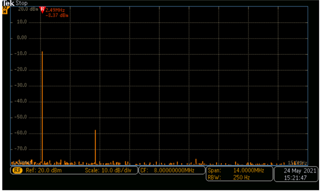
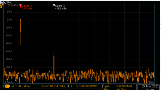
At the output of DAC3282, we are getting 2nd and third harmonics. These harmonics get amplification in our Transmitter chain as we are using amplifiers in the latter stage.

Our signal BW is from 500Khz - 20Mhz, DAC Sampling rate 210MSPS ( Using x2 Interpolation). DAC gain is X66. In a later stage, we are using LPF cutoff 28Mhz. 

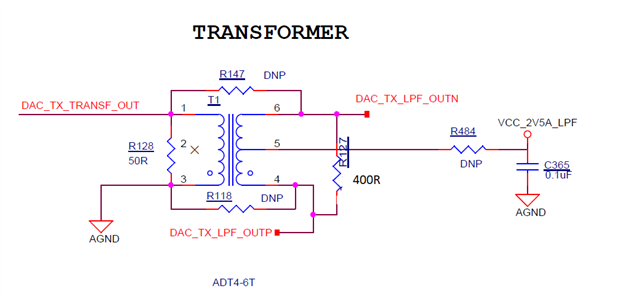
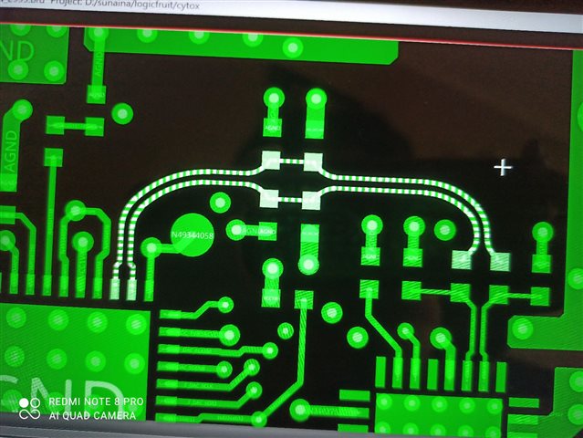
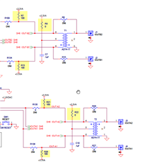
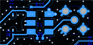
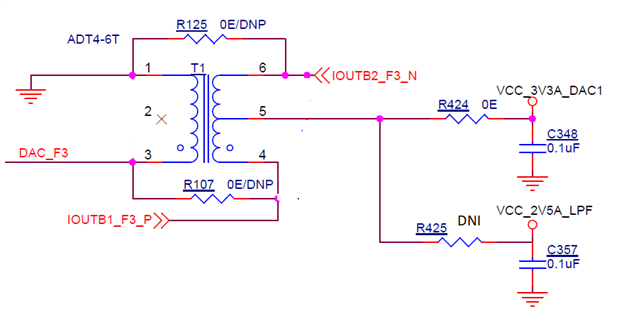
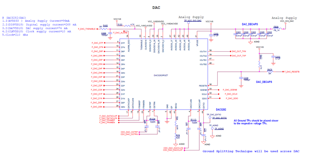
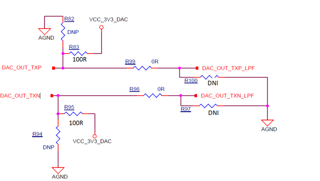
PFB Schematics of DAC3282 and DAC front-end circuitry. DAC CLK is LVPECL 210Mhz.

Please suggest review points to fix this issue as earliest.

Regards 

Balvan Singh

  • Hi Balvan,

    Please advise the level that you are seeing. For such low IF from .5MHz to 20MHz, the expected level for HD2 and HD3 should be > 80dBc. You may use a low frequency balun to help suppress HD2 and HD3. Please find attached report and suitable balun recommended.

    DAC3283 HD3 Performance - Copy.ppt

  • Hi Sir We are already using ADT4-6T after LPF but the issue is still there 

    Value of R127 is taken 400R here but we have tried changing R127 to 200R and r128 to 100R but issue still persists.

  • Hi,

    The HD2 is primarily due to the external circuit imbalance. The signal out of the DAC output is should be balanced as best as it can. Please double check your layout to keep the differential traces short and routed in a balanced fashion, and observe the single ended output out of the balun. 

    Thanks. 

  • Hi Sir 

    We are taking Care of this thing in layout and routing .still we are facing the second harmonic issue from DAC.PFB harmonic image for your references.The result is not matching with the datasheet. Can u please suggest some point to fix this issue as soon as possible.

    thanks

  • PFB Layout image for your references

  • Hi ANy update for the same . 

    we are not getting expected result which mentioned in datasheet

  • Hi,

    In reviewing your schematic, your output network is not matching the EVM. The EVM also has the 4:1 transformer. You can see the center tap of the transformer is biased at 3.3V through 0ohm resistor. There is no need for the 400ohm parallel resistor. You will need the 100ohm pull-up to 3.3V. 

    Please note that the 3.3V must be well filtered power supplies. Any noise and distortion on the power supply will be coupled into the output. I see you only have option to bias the center tap to 2.5V. This will not meet the output compliance voltage of the DAC.

    I cannot interpret your layout. All the terminations on your layout are far away from the DAC output. In general, the terminations (both source and load) should be as closely coupled as possible. Please refer to our DAC3283 EVM layout for reference. 

    https://www.ti.com/lit/zip/slar052

    There is no other way to improve HD2. The DAC itself has > 80dBc of HD2 on the analog core performance. Again, HD2 is purely due to external components. If the DAC is not properly biased at the compliance voltage, HD2 could degrade. Please double check DAC3282 output compliance voltage again the datasheet spec.

    I do not not see how you are probing the DAC output. There is no probe point in your layout. In our EVM, the transformer output is connected to SMA to be observed on the spectrum analyzer. You will need to make sure the spectrum analyzer itself is not introducing HD2's. You will need to adjust the spectrum analyzer attenuation setting to avoid spectrum analyzer distortion.

    Please inject a 10MHz signal from your signal source, and check the spectrum analyzer. If you are also seeing significant HD2s, then your spectrum analyzer need to be adjusted.

    Please consider ordering an EVM and perform the testing on it. Please also refer to EVM layout and follow it. Thank you

  • Hi Kang thank you for your response and time for review our design.

    We have our old board with the same DAC and Transformer. In that board, we have given the option for 3.3V.

    PFB image 

    I have tried those points suggested by you as making 400R DNI and giving center tap 3.3V . But no improvement in SFDR.

    for measuring, I just isolated the later RF chain from ADT4-6T stages by removing a connecting resistor. And probing one end of that resistor. through CRO probe.

    For CRO concerns, we don't have a clean signal generator to verify the signal. The one which we have a signal generator i tried providing attenuation but both signal and harmonic get attenuated and no change in SFDR.

    Any other suggestions?

    Thanks 

  • WE are getting this result after transformer with you suggested settings.PFB image

  • Balvan,

    In our lab, we connect to the R&S or Keysight spectrum analyzer directly through SMA connector cable. Those equipment have sufficient linearity and does not add additional distortions. 

    I am not certain about your test methodology with CRO. You have to make measurements and convince yourself that you are not measuring the distortion from your test setup. I do not have other guidance as the DAC itself and the balun itself do not generate such high HD2. This should be a fairly straight-forward measurement. 

  • Hi Kang, Thank you for the support.

    Maybe it's due to CRO. Can you please tell me how much minimum  BW require for measuring DAC out put of 20Mhz.(Dac clk is 210Mhz)

  • Hi Balvan,

    It is not the bandwidth of the scope, rather, the linearity of the scope capability as the CRO is introducing its own linearity limitation. You will need to find a better equipment to measure the true capability of the DAC3282.

    -Kang

  • Thank you Kang for your support

  • no problem. good luck