This thread has been locked.

If you have a related question, please click the "Ask a related question" button in the top right corner. The newly created question will be automatically linked to this question.

ADS1231: Problem with Output Codes

Part Number: ADS1231
Other Parts Discussed in Thread: MSP430F5529

Hello,

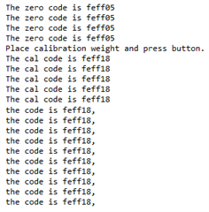
I am facing some problems regarding the output codes of the ADS1231. According to Table 3 in the ADS1231's datasheet, I should be receiving a code of 0x00 when there is no weight on the scale. As the weight increases, the code should also increase accordingly. However, based on the results I have obtained (attached below), the outputted codes do not function as intended. The user-specified calibration weight is 216 grams, which I manually inputted into the code. As you can see from the results, once this weight is added to the scale, the output code only changes by 0x14 from the zero code to the calibration code. Subsequently, the step resolution between each outputted code is quite large (since 0x14 = 20, 216/20 ~= 10 grams per step), causing the weight scale to be imprecise. As I add more weight to the scale, the code begins to increase as intended until it reaches a threshold of roughly 500 grams. Once it reaches this weight, however, the code decreases by a relatively significant amount (and the weight becomes negative since the output code is now smaller than the zero code), although it should keep increasing as more weight is added. With enough force on the scale, the code begins to increase again.

To summarize my questions, how can I access a wider range of ADC output codes so the resolution between each digital output is more precise? Does it have to do with the sensitivity of my weight scale platform / load cells? Also, why do the outputted codes start to decrease when a certain threshold is reached, even though they should continuously increase as more weight is added? Finally, why isn't the zero code 0x00?

I've attached the polling code as well as the calibration procedure. Any help is greatly appreciated.
 if ((P1IN & 0x08) == 0)
        {
            while (!(UCB0IFG & UCTXIFG));
            UCB0TXBUF = 0x21;
            while (!UCRXIFG);              // if RX operation is not complete
            data1_z = UCB0RXBUF;

            while (!(UCB0IFG & UCTXIFG));
            UCB0TXBUF = 0x22;
            while (!UCRXIFG);
            data2_z = UCB0RXBUF;

            while (!(UCB0IFG & UCTXIFG));
            UCB0TXBUF = 0x23;
            while (!UCRXIFG);
            data3_z = UCB0RXBUF;

            while(!(UCB0IFG & UCTXIFG));
            UCB0TXBUF = 0x24;

            code_z = (data1_z << 16) + (data2_z << 8) + data3_z + 0x800000;
            code_z &= 0x00ffffff;
            printf("The zero code is %lx\n", code_z);
        }
m = weight_c / (code_c - code_z);
weight_z = -1 * m * code_z;
weight = (m * code) + weight_z;

  • Hi Yamen,

    It appears that the calibration weight used is very close to the 0 value which makes the calibration slope very difficult to calculate.  Generally you would want to place a weight on the scale that is approaching the maximum weight for the load cell.

    I personally do not try to shift the data from binary 2's complement to unipolar format as this just becomes confusing in the end.  So for me to figure out what might be happening I need to know some more detail. 

    • What are the voltages for the ADS1231 AVDD and the reference?
    • What is the sensitivity of the load cell in mV/V? 
    • What is the maximum weight that can be applied to the load cell to reach the full-scale output? 
    • Can you share your schematic?

    After I have this information we can work on how to achieve the expected results.

    Best regards,

    Bob B

  • Hi Bob,

    I'm using a configuration of 4 load cells. They all have an output sensitivity of 1 mV/V, and each can support 40-50 kg.

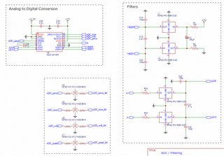
    VREFP, AVDD, and the excitation voltage of the bridge share a +5V DC voltage (which I see might be problem), and VREFN is connected to ground. The schematic is shared below. The ADS1231 is connected to a MSP430F5529 microcontroller. Thank you for your help.

  • Hi Yamen,

    Can you explain in more detail how the load cells are connected together (forming a bridge or in parallel)?  Also, what type of load cells are you using?  Are they 3-wire, 4-wire or 6-wire load cells?

    Let's say you have a single 50kg load cell with a 1mV/V sensitivity and you excite that load cell with 5V.  The load cell output at 5V for a full-scale reading would be 5mV.  The ADS1231 full-scale range is +/- 19.5mV.  So 5mV output would only be utilizing about 1/8th of the full-scale range or 1/8 the total available codes.  And the total available codes will depend on the best case resolution for the ADS1231 with noise-free operation.  This will depend on the data rate used.  At 10sps the resolution is 17.4 bits and at 80sps it is 15.9 for 5V excitation/reference.  Calibrating with 216g for a 50kg load cell is like calibrating the noise.  Your calibration weight should be closer to 50kg to get a good calibration value for the scale slope otherwise noise will be a significant factor.

    You need to make sure that when making these large calculations that you do not have an issue with numeric overflow, especially with floating point calculations.  You may need to use doubles instead of integers.

    The Analog Engineers Calculator now has a Bridge Sensor section under the Data Converters drop-down menu.  This may be useful to help you determine the amount of resolution available in a best case scenario.

    Best regards,

    Bob B

  • Hi Bob,

    The load cells have 3 wires each and are connected to form a full bridge. If the resolution at 10 sps for a 5V excitation source is 17.4 bits, does that mean the most significant 6.6 bits will not change, assuming the full-scale range is used? Will the full-scale load cell output increase to 20 mV with my full bridge configuration?

    I tried setting the calibration weight to 52 kg, considering the full capacity of the configuration is 200 kg (4 load cells * 50 kg), but the most significant byte of the output code still does not change.

    The only values that are integers are the codes that the ADC outputs since they are digital signals and can't be bitwise shifted otherwise. All other variables used during the calibration computations are doubles.

  • Hi Yamen,

    I think it would be best to keep the output as binary 2's complement.  Make code_z a signed integer and when combining the 3 data bytes do something similar to:

    code_z = (data1_z << 16) + (data2_z << 8) + data3_z;

    code_z = code_z << 8;

    code_z = code_z >> 8;  // this will take the 24-bit value and sign-extend the negative bit to 32-bit integer

    Unfortunately you will not get an increase in the output of the load cells.  The maximum output will be 200kg for the scale, but the sensitivity will remain at 1mV/V.  As to the scale output if you have a good meter that can measure the output of the bridge, you should see about 1.5mV for the 52kg load.  This would be around 0x09D495 from the ADS1231.  If you get something different on the bridge output, then maybe the bridge is wired incorrectly.

    As far as the noise-free bits, the 17.4 bits is the best the ADC can do at the 5V excitation/reference for 10sps data output rate.  This means that over the full-scale range of the ADC, you could potentially see 172950 codes.  But this is assuming the full-scale range.  The maximum scale output will be about 1/8th of the full-scale range, which reduces the number of codes within the measurement range to 21619.  200kg/21619 codes ends up around 10g resolution.

    Best regards,

    Bob B

  • Hi Bob,

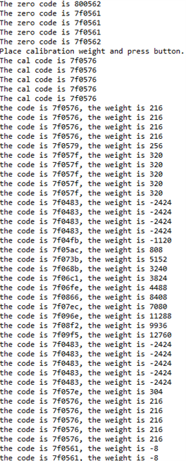
    The codes from the ADS1231 are always negative when I keep the output as binary 2's complement, regardless of the polarity of the bridge's output. Using 52 kg as the calibration mass, the output codes barely change when the calibration load is placed on the scale, as you can see in the results below.

    The data I shared in the original post of this thread had a larger range of codes, but still not enough to meet the expected resolution (0x7f096e - 0x7f0561 = 0x40D = 1037 codes).

    Does the platform that sits on the load cells affect the results? My codes did not change whatsoever when placing the calibration load on a metal platform, but I was able to obtain the results below by changing the material.

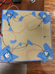
    Here is an image of my load cell configuration:

  • Hi Yamen,

    The bridge appears to be connected together correctly, but it will make a difference on which leads are used when connecting to the ADC and excitation.  Which color wire are you using for each connection to EXC+, EXC-, SIG+ and SIG-?

    The platform weight will make a difference, but material type should not.

    Best regards,

    Bob B

  • Hi Bob,

    blue -> EXC+

    green -> SIG-

    gray -> EXC-

    white -> SIG+

    Does the platform weight affect the sensitivity of the scale, or is it just additional mass that must be accounted for when calibrating the offset?

  • Hi Yamen,

    Those connections provided would also be the way I would connect.  It is not at all clear why your codes are negative.  I would verify the voltages at all of the connections relative to GND.  The blue wire should be 5V, the gray wire at 0V and the remaining wires should be 1/2 of the excitation voltage (2.5V).  

    Next check the voltages from SIG+ to SIG- with an external voltmeter without the platform.  This should be very close to 0V.  Next, place the platform on the load cells and measure the voltage again.  There should be a slight increase in the voltage.  Depending on your meter it may not be significant enough to measure.  Place the 52kg weight on the platform and measure again with the external meter.  You should now see something measurable around 1.2mV.  Let me know what you see for each of those measurements.

    As to the added platform weight, this will reduce the total capacity of the scale, but not the sensitivity.  Let's say the platform were to weigh 1kg, then the maximum scale weight would be 200kg - 1kg or 199kg.

    Best regards,

    Bob B

  • Hi Bob,

    The voltages of the four wires with respect to GND check out. Here are my results after measuring the potential between SIG+ to SIG-:

    no load -> 0.9639 mV

    platform load -> 1.1055 mV

    52 kg load -> 3.9727 mV

  • Hi Yamen,

    At this point there is either a connection issue at the ADC or something is configured improperly.  I suppose it is always possible that the ADC was damaged as well. 

    Make sure that none of the digital pins are floating on the ADC and verify the voltages for each pin connected to the micro GPIO.  Another potential issue is the connection at the low-side switch.  You may want to connect the EXC- directly to GND to see if that makes a difference.

    Let me know the voltages at each of the ADS1231 pins so I can know how the device is being configured.  I would also suggest looking at the data coming out of the ADS1231 to make sure that it is being read properly in your code.  With an oscilloscope or logic analyzer check the DRDY/DOUT signal to see if it pulses at the data rate selected.  This tells us that the internal clock is working as expected.

    The SIG+ and SIG- values seen at the bridge should also be seen at the inputs of the ADC.  Measure across the inputs of the ADC at the input cap and that is usually easier to measure than at the device pins.

    When reading the conversion data in your code, verify that the data matches precisely with what is transmitted from the ADS1231.

    Best regards,

    Bob B

  • Hi Bob,

    I verified that the data on the oscilloscope matched with what is transmitted by the ADS1231. I also measured the voltage at each of the ADS1231 pins. Here are the results:

    DVDD -> +3.3V

    GND / CLKIN / SPEED / SW -> 0

    CAP (5) -> 2.53

    CAP (6) -> 2.47

    AINP -> 2.5

    AINN -> 2.5

    VREFP -> 5.02

    VREFN -> 0

    AVDD -> 5.02

    PDWN -> 3.3

    The EXC- signal is sent directly to the SW pin of the ADS1231 and no where else, as shown above.

    I tried using an interrupt-driven program instead of my previous polling code, and I obtained output codes with a significantly larger range than before (the difference between the highest and lowest output being 0x2fff). However, for both programs, the output code when no load is placed on the load cells equates to roughly 0.15 mV, even though the corresponding bridge's output is ~1 mV. Here is my interrupt code:

    #if defined( __TI_COMPILER_VERSION__ ) || defined( __IAR_SYSTEMS_ICC__ )
    #pragma vector = PORT1_VECTOR
    __interrupt void Port_1(void)
    #elif defined(__GNUC__)
    void __attribute__ ( (interrupt(PORT1_VECTOR) ) ) Port_1 (void)
    #else
    #error Compiler not supported!
    #endif
    {
        switch ( __even_in_range( P1IV, P1IV_P1IFG7 ))
        {
            case P1IV_P1IFG1:
                ready_for_cal = true;                                   // set ready for calibration flag
                P1IFG &= ~BIT1;                                         // clear interrupt flag
                break;
    
            case P1IV_P1IFG3:
                while (!(UCB0IFG & UCTXIFG));
                UCB0TXBUF = 0x21;
                while (!UCRXIFG);              // if RX operation is not complete
                data1 = UCB0RXBUF;
    
                while (!(UCB0IFG & UCTXIFG));
                UCB0TXBUF = 0x22;
                while (!UCRXIFG);
                data2 = UCB0RXBUF;
    
                while (!(UCB0IFG & UCTXIFG));
                UCB0TXBUF = 0x23;
                while (!UCRXIFG);
                data3 = UCB0RXBUF;
    
                while (!(UCB0IFG & UCTXIFG));
                UCB0TXBUF = 0x24;
    
                code = (data1 << 16) + (data2 << 8) + data3;
                printf("The code is %lx\n", code);
    
                P1IFG &= ~BIT3;                                        // clear interrupt flag
                break;
    
            default:
                break;
        }
    }