Hi,
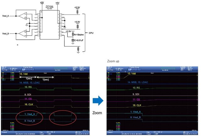
The customer's DAC will show an unintended output voltage after POR. Increasing the "time constant" of the RS Pin will solve this problem.
VDD = 5V
CS, CLK = pull up 3.3V
LDAC = Low fixed
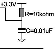
RS: 10k / 0.01uF
The power sequence is 5V-> 3.3V, and after 5V is completely turned on, 3.3V is turned on.
In this case, CS and RS start up at the same time, but RS is slightly slower.

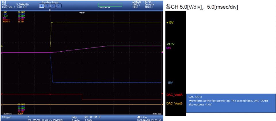
Changing RS to 220k ohms / 0.01uF will improve it, so it is possible that the reset was released and LDAC was enabled before CS reached 3.3V.
Because LDAC is fixed at Low.
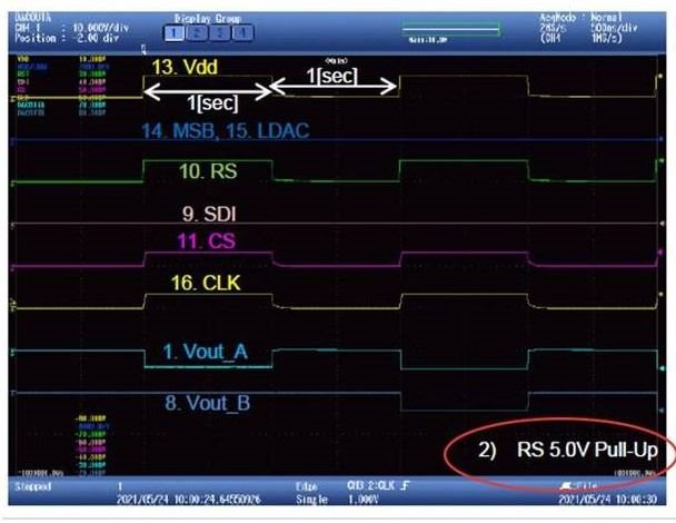
However, CLK has only one rise during this time.
18 Bit is required for data loading.
Is DAC OUT updated with LDAC = Low even if the number of clocks is 18 bits or less? (In this case, when CS = Hi)
Also, if this phenomenon occurs without writing a value to the DAC register even once,
Is DAC OUT indefinite?
Best Regards,
Hiroshi