Hi,
I was trying o use DAC8571 using an Arduino using the library https://github.com/baku1413/DAC8571 but could not get it working.
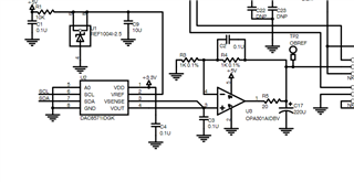
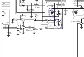
below is my DAC circuit

This thread has been locked.
If you have a related question, please click the "Ask a related question" button in the top right corner. The newly created question will be automatically linked to this question.
Hi,
I was trying o use DAC8571 using an Arduino using the library https://github.com/baku1413/DAC8571 but could not get it working.
below is my DAC circuit

Hi Samarth,
I am not an expert in Arduino coding, but ensure that you are writing a 4 byte command to the DAC. For example, you would want to address the correct update mode (0x10 - for immediate update) and you need a 16-bit value. For example, writing:
<ADDR> <COMMAND> <DAC VALUE MSB> <DAC VALUE LSB> will update the device. If you were to scope the cammand, you would see:
0x98 0x10 0x7F 0xFF if you wanted to write the value 0x7FFF to the DAC. I recommend you use a logic analyzer or scope to confirm the correct value is being written.
Thanks,
Paul
the DAC I am able to code till 5v output but it shows 5v sometimes and sometimes 0.6v .
I am not able to code it to a fixed value every time I code?
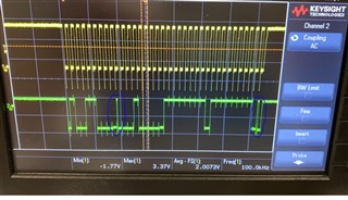
green SDA
yellow SCL.
my arduino code:
Wire.begin();
Wire.beginTransmission(0b01001100); //address
Wire.write(0b00010000); //set immediate update
Wire.write(0xff); // max
Wire.write(0xff); // max
Wire.endTransmission();
}


Hi Samarth,
Your I2C sequence from the scope shot looks correct and it looks like the DAC is acknowledging where it should. Your reference is 2.5V. Are you able to probe the DAC output and let us know if you see 2.5V on the DAC output when you write 0xFFFF? Do you see 1.25V on the DAC output when you write mid-code (0x8000)? Let's try to verify if the DAC is working properly first.
Best,
Katlynne Jones
hi,
Yes, I am able to get 5v at 0xffff and 2.5v at 0x8000. This is because I have an opamp before my output, as shown. The issue is the DAC updates only when I turn on the power and write it instaniously.
After that, if I try to write or update, my signals are correct but it shows 0.6v only at the output AND DOES NOT UPDATE.
So as said before,it codes sometimes and updates,but most of the time it does not respond to the above-shown signals.
Hi Samarth,
For some additional context to help the debugging process, do you see the 0.6V at the output of the op amp when 0xFFFF and when 0x8000 is written to the DAC?
Are your subsequent I2C sequences exactly the same as the first? With the complete <ADDR> <COMMAND> <DAC VALUE MSB> <DAC VALUE LSB>.
What is the voltage scale of your scope shot for SDA and SCL? Are both signals using 3.3V logic?
Best,
Katlynne Jones
Hi Samarth,
Going off of my previous reply, I'd like to know how the DAC is operating. Can you please measure a few codes between 0x000 and 0xFFFF at the output of the DAC (pins 3 and 4) and let me know the voltages you see. We will need to debug your schematic one part at a time to pinpoint where it is going wrong.
Thank you for you patience,
Katlynne
Hi,
Wire.begin();
Wire.beginTransmission(0b01001100);
Wire.write(0b00010000); // sends five bytes
Wire.write(0x00);
Wire.write(0x00); // sends one byte
Wire.endTransmission();
the above code runs once and output as follows
for ffff output,
pin1=3.3v
pin2=2.5v
pin3=2.5v
pin4=2.5
pin5=.1v
pin6=3.3v
pin7=3.3v
pin8=.1v
but it takes like 4 mins to reach pin 3 and 4 to 2.5v.which is so weird.i keep measuring for 4 mins and at somepoint it rises from 0.1 to 2.5v
for 0000 output
pin1=3.3v
pin2=2.5v
pin3=.1v
pin4=.1
pin5=.1v
pin6=3.3v
pin7=3.3v
pin8=.1v
Hi Samarth,
Do you see a similar behavior when writing 0x8000 to the DAC? What do you see on the DAC output when the op amp output was seeing 0.6V? Also, C3 on the DAC output is larger than the max value given in the datasheet. Can you try removing this and let us know your results? The max value is 1000pF with a 2kΩ load. You are using 100nF.
Thank you,
Katlynne Jones