This thread has been locked.

If you have a related question, please click the "Ask a related question" button in the top right corner. The newly created question will be automatically linked to this question.

ADS8685: REFCAP Pin Capacitor ESR

Part Number: ADS8685

Section 10.1 for layout guidelines mentions need a capacitor with ESR less that 0,2 Ohms for REFCAP pin (10uF one)

We are considering a cap with Impedance under 0.2Ω for 2kHz~2GHz .

From the layout from section 10.2 of the DS. 

AVDD and DVDD should be separated, but GND should be, ideally, a solid layer, connected to device by vias, right?

  • Hi Darren,

    The typical value of this resistor is between 0.1ohm to 2ohm. The signal on the Reference is DC, so the resistor in your graph is higher than 3ohm.

    The small resistance is helpful to make the buffer stable. You can use an external small resistor for this, please see the circuit and description in the app note below:

    https://www.ti.com/lit/ug/tidu012c/tidu012c.pdf

    A solid ground plane is good and easy for most applications.

    Best regards,

    Dale

  • Hi Dale,

    So...too small a resistance and you could have stability issues with the driving amplifier; trying to drive too much capacitance.
    Too high a resistance and you might not be able to dampen fluctuations on the line fast enough, leading to output code variations.

    From the material you shared:

    The capacitor CBUF_FLT affects the stability of the driving amplifier, therefore it is recommended to use a series resistor, RBUF_FLT to isolate the amplifier output and make it more stable. The value of RBUF_FLT is dependent on the output impedance of the driving amplifier as well as on the signal frequency. Typical values of RBUF_FLT range between 0.1 Ω to 2 Ω and the exact value can be found by using SPICE simulations. It is recommended to use the smallest possible values for RBUF_FLT to avoid any voltage spikes at the reference pin, which can potentially affect the conversion accuracy.

    From this, I understand:
    lower resistance is better because it allows more charge to travel to the cap faster, which helps reduces spikes,
    A higher resistance is better because it isolates the opamp output from the cap, helping keep the amplifier in it's stable operating region

    But at DC, since there are no "sudden" charge movements, a higher resistance (3.6Ω) shouldn't be an issue, correct?

    The concern is whether the OPAMP can drive the capacitance with ~10mΩ of series resistance, at the higher frequencies, right?

    If it can't, then series resistance (0.1Ω to 2Ω) needs to be added, and/or capacitance reduced, to help keep the reference buffer driving amplifier in it's stable operating region.

    Is that understanding correct?

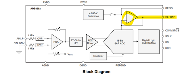
    EDIT: When using the Internal Reference, there is an internal buffer which buffers the internal reference voltage and provides this to the ADC section. (Figure 7-7 in the DS) If the characteristics of this buffer are known to us, then is series resistance (0.22Ω like in EVM) needed here for stability of this internal buffer, paired with the recommended external capacitance? The DS doesn't make any mention about needing this series resistance...only that the caps ESR < 0.1Ω...

  • Hi Darren,

    The higher resistance does mean better to make the amplifier stable. The best value can be found from SPICE simulation. The reference voltage is DC signal, however the signal is also connected to the capacitor array and switches on the ADC, so it's should be settled during limited time and still have charge injection.

    Both solutions using a capacitor with smaller ESR or inserting a smaller resistor work. If your capacitor can meet the recommendation, you can use it. However, inserting a smaller resistor is a simple way to achieve it so that this is usually used on EVM boards.

    Regards,

    Dale

  • Hi Dale,

    You mentioned: >> Both solutions using a capacitor with smaller ESR or inserting a smaller resistor work.

    I am a little confused. I understand the "or" means:

    a) use a capacitor with lower ESR
    b) use a capacitor with higher ESR, but insert a smaller resistor

    The DS Recommends a capacitor with less than 0.2Ω ESR...is this to allow flexibility in adding series resistance if needed?
    Or is there another reason?

    [1]
    I understand this may be to make sure the series resistance is low-enough, so the necessary charge can be drawn from the cap in the required time. Is that understanding correct?

    [2]
    Then, if the required charge can be delivered to the ADC in the required time, we can increase series resistance to help isolate the buffer, and improve stability (if needed). The goal is to balance these two, right?

    There are two decoupling capacitors used for the REFCAP pin. The first is a small, 1-μF, 0603-size ceramic capacitor placed close to the device pins for decoupling the high-frequency signals and the second is a 10-μF, 0805-size ceramic capacitor to provide the charge required by the reference circuit of the device. A capacitor with an ESR less than 0.2 Ω is recommended for the 10-μF capacitor. Both of these capacitors must be directly connected to the device pins without any vias between the pins and capacitors.

    Our EVM uses GRM21BR61C226ME44 
    DC: 1.4Ω
    1kHz ~ 2GHz: <0.2Ω

  • Hi Darren,

    The ESR of a capacitor is usually not high as you thought in b). Inserting a smaller value resistor is commonly used on our EVM board, you can find R25 on ADS8681EVM. The R25 (0.22ohm) and C12 (22uF) together can be considered as a RC snubber network, it's helpful to suppress high frequency oscillations in the amplifier output stage. Such RC snubber network is often used in all kind of op-amp applications that requires driving reactive loads.

    [1]: Correct, the reference buffer with smaller series resistor will have a lower output impedance and it will be able to recharge the switch capacitive load of the ADC and settle the signal faster.

    [2]: Making amplifier stable does not mean that it requires a higher value resistor. The stability is related to the amplifier's output impedance and frequency. See Precision Labs - Op Amps:  Stability.

    As for the component values, you can find exact value by using a simulation or adjusting it from measurement. However, the simplest way is, just use the recommended values and do not worry about calculating them .

    I hope this helps.

    Regards,

    Dale

  • Dale: just use the recommended values and do not worry about calculating them .

    The Datasheet makes no mention about requiring some small resistance between REFCAP pin and it's decoupling capacitance to help with high frequency oscillations of the amplifier's output stage. Because the DS didn't mention this resistor, my customer does not have it in their design. They were following the only recommendation they saw for the capacitor; that is:

    DS: A capacitor with an ESR less than 0.2 Ω is recommended for the 10-μF capacitor

    To avoid confusion, let me try and re-phrase my question; sorry if it wasn't clear.

    Question:

    [1] Why does the DS recommend the capacitor have ESR less than 0.2Ω, if we also recommend adding more series resistance? (0.22Ω like in the EVM)

    [2] There is no SPICE model available for this internal buffer "opamp", so no way to simulate what the response would be for a given DR, etc. How do you recommend doing a simulation with no known characteristics of the internal buffer amp?

  • Hi Darren,

    RC snubber network is helpful to add the buffer's stability. Let me schedule a meeting with you for communication early next week.

    Regards,

    Dale

  • Hi Darren,

    Since we had a communication offline, I'm going to close this thread. You can contact me directly if you have further questions.

    One clarification:   Since we are looking at transient behavior for the signal on the reference and the internal conversion clock on ADS8685 is 16MHz, so we need to consider the ESR of capacitor on the reference buffer (REFCAP) at 16Mhz instead of DC.

    Thanks&regards,

    Dale