


hi all ,
"Read zero in channel 2 after about 10 s "
i have been test step:
a. use single mode?
b. use the TEST mode
it seem HW(ADS1292R status error or timing issue ? how to setting it .
Can you give me some advice as to whether?
1.HW
i reference datasheet circuit .
2.SW , SPS 1k hz, read data 5ms interval
init and read function
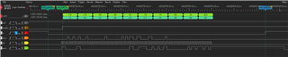
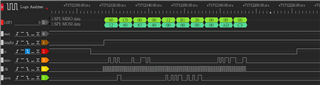
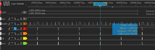
3. Waveform ( normal ; failed) and overview
typedef enum
{
    // Device Settings (READ ONLY REGs)
    ECG_REG_ID          = 0x00,
    // Reg ID Control Register: Factory programmed, Read only register
    // Global settings accross channels
    ECG_REG_CONFIG1     = 0x01,     // Configuration 1 Reg
    ECG_REG_CONFIG2     = 0x02,     // Configuration 1 Reg
    ECG_REG_LOFF        = 0x03,     // Lead-Off Control Reg
    // Channel-specific settings
    ECG_REG_CH1SET      = 0x04,     // Channel 1 Settings
    ECG_REG_CH2SET      = 0x05,     // Channel 2 Settings
    ECG_REG_RLD_SENS    = 0x06,     // Right Leg Drive Sense Selection
    ECG_REG_LOFF_SENS   = 0x07,     // Lead-Off Sense Selection
    ECG_REG_LOFF_STAT   = 0x08,     // Lead-Off Sense Status
    // GPIO and other Registers
    ECG_REG_RESP1       = 0x09,     // Respiration Control Register 1
    ECG_REG_RESP2       = 0x0A,     // Respiration Control Register 1
    ECG_REG_GPIO        = 0x0B,     // General Purpose I/O Register

    ECG_REG_COUNT       = 0x0C      // Reg Count
} ECG_REG_MAP;

// Config2 register: Configures ADC sample rate & mode (continuous / one shot)
typedef enum
{
    // Bits 0 - 2 are used for oversampling ratio for both channels 1 & 2
    // fMod (128 KHz) / one of these #s.
    // (Ex /64 = 128K / 64 = 2KHz ECG sampling)
    ECG_CONFIG1_DIVBY_1024  = 0x00,
    ECG_CONFIG1_DIVBY_512   = 0x01,
    ECG_CONFIG1_DIVBY_256   = 0x02,
    ECG_CONFIG1_DIVBY_128   = 0x03,
    ECG_CONFIG1_DIVBY_64    = 0x04,
    ECG_CONFIG1_DIVBY_32    = 0x05,
    ECG_CONFIG1_DIVBY_16    = 0x06,
    // Bits 6-3 are constants, and must be set to 0
    ECG_CONFIG1_CONSTANT    = 0x00,
    // Bit 7
    ECG_CONFIG1_SINGLE_SHOT = 0x80,
    ECG_CONFIG1_CONTINUOUS  = 0x00
} ECG_CONFIG1_REG;

#define ECG_CONFIG1_NORMAL  (ECG_CONFIG1_CONTINUOUS |ECG_CONFIG1_DIVBY_128)


// Config2 register: Configures the TEST signal, CLK, reference and LOFF buffer
typedef enum
{
    // Bit 7 must always be set high & BIT2: Must always be set to 0
    ECG_CONFIG2_CONSTANT                = 0x80,
    // Bit 6: PDB_LOFF_COMP
    ECG_CONFIG2_PDB_LOFF_COMP_ENABLED   = 0x40,
    // BIT5: PDB_REFBUF
    ECG_CONFIG2_PDB_REFBUF_ON           = 0x20,
    // BIT4: VREF)2.42V or 4.033V. We can only have a 2.42
    // reference since the 4 V ref requires a 5VDC supply
    // ECG_CONFIG2_VREF_4033             = 0x10,
    // BIT 3: CLK_EN internal Osc is test used in our design.
    // select external/internal Osc
    ECG_CONFIG2_INTEROSC_ON = 0x08,
    // BIT1: TEST signal
    ECG_CONFIG2_TEST_ON                 = 0x02,
    // BIT 0: TEST_FREQ: DC / 1Hz
    ECG_CONFIG2_TEST_FREQ_1HZ           = 0x01
} ECG_CONFIG2_REG;

#define ECG_CONFIG2_TEST    (ECG_CONFIG2_CONSTANT \
                            | ECG_CONFIG2_PDB_REFBUF_ON | \
                            ECG_CONFIG2_TEST_ON | ECG_CONFIG2_TEST_FREQ_1HZ)
#define ECG_CONFIG2_NORMAL  (ECG_CONFIG2_CONSTANT | \
                             ECG_CONFIG2_PDB_LOFF_COMP_ENABLED |\
                            ECG_CONFIG2_PDB_REFBUF_ON  \
                             )

typedef enum
{
    // Bit 7: Channel power up / down
    ECG_CHAN_SET_PWR_DOWN               = 0x80,
    ECG_CHAN_SET_PWR_UP                 = 0x00,
    // BITS 6-4:  GAIN
    ECG_CHAN_SET_GAIN_6                 = 0x00,  // Default
    ECG_CHAN_SET_GAIN_1                 = 0x10,
    ECG_CHAN_SET_GAIN_2                 = 0x20,
    ECG_CHAN_SET_GAIN_3                 = 0x30,
    ECG_CHAN_SET_GAIN_4                 = 0x40,
    ECG_CHAN_SET_GAIN_8                 = 0x50,
    ECG_CHAN_SET_GAIN_12                = 0x60,
    // BITS 3:0 Channel input selection
    ECG_CHAN_SET_INPUT_NORMAL           = 0x00,
    ECG_CHAN_SET_INPUT_SHORTED          = 0x01,
    ECG_CHAN_SET_INPUT_RLD              = 0x02,
    ECG_CHAN_SET_INPUT_MVDD             = 0x03,
    ECG_CHAN_SET_INPUT_TEMP             = 0x04,
    ECG_CHAN_SET_INPUT_TEST             = 0x05,
    ECG_CHAN_SET_INPUT_RLD_DRP          = 0x06,
    ECG_CHAN_SET_INPUT_RLD_DRM          = 0x07,
    ECG_CHAN_SET_INPUT_RLD_DRPM         = 0x08,
    ECG_CHAN_SET_INPUT_ROUTE_IN3        = 0x09
} ECG_CHAN_SETTINGS_REG;

#define ECG_CH_OFF              (ECG_CHAN_SET_PWR_DOWN +  \
                                ECG_CHAN_SET_INPUT_SHORTED)
#define ECG_CH_DRP              (ECG_CHAN_SET_INPUT_RLD_DRP)
#define ECG_CH_RLD              (ECG_CHAN_SET_PWR_UP |ECG_CHAN_SET_INPUT_RLD)
#define ECG_CH_DRM              (ECG_CHAN_SET_INPUT_RLD_DRM)
#define ECG_CH_DRPM             (ECG_CHAN_SET_PWR_UP + \
                                ECG_CHAN_SET_INPUT_RLD_DRPM)
// If the gain is ever changed then the
// ECG_CONVERSION_FACTOR which assumes a gain of 6 should also be changed.
#define ECG_CH_NORMAL           (ECG_CHAN_SET_PWR_UP | \
                                ECG_CHAN_SET_INPUT_NORMAL)

typedef enum
{
    // Bits 7 & 6: Chop Freq
    ECG_RLD_SENS_CF_DIV_16              = 0x00,
    ECG_RLD_SENS_CF_RES                 = 0x40,
    ECG_RLD_SENS_CF_DIV_2               = 0x80,
    ECG_RLD_SENS_CF_DIV_4               = 0xC0,
    // Bit 5:  Buffer Power
    ECG_RLD_SENS_PDB_RLD_EN             = 0x20,
    // Bit 4: RLD_LOFF_SENSE
    ECG_RLD_SENS_RLD_LOFF_SENSE_EN      = 0x10,
    // Bit 3: RLD2N Ch2 RLD neg inputs
    ECG_RLD_SENS_RLD2N_CONNECTED        = 0x08,
    // Bit 2: RLD2P Ch2 RLD pos inputs
    ECG_RLD_SENS_RLD2P_CONNECTED        = 0x04,
    // Bit 1: RLD1N Ch1 RLD neg inputs
    ECG_RLD_SENS_RLD1N_CONNECTED        = 0x02,
    // Bit 0: RLD1P Ch1 RLD pos inputs
    ECG_RLD_SENS_RLD1P_CONNECTED        = 0x01
} ECG_RLD_SENS_REG;

#define RLD_SENS_USE_CH2        (ECG_RLD_SENS_PDB_RLD_EN \
                                | ECG_RLD_SENS_RLD2N_CONNECTED \
                                | ECG_RLD_SENS_RLD2P_CONNECTED)
#define RLD_SENS_USE_CH1        (ECG_RLD_SENS_PDB_RLD_EN \
                                | ECG_RLD_SENS_RLD1N_CONNECTED \
                                | ECG_RLD_SENS_RLD1P_CONNECTED)

#define RLD_SENS_USE_CH1_2        (ECG_RLD_SENS_PDB_RLD_EN \
                                | ECG_RLD_SENS_RLD1N_CONNECTED \
                                | ECG_RLD_SENS_RLD1P_CONNECTED \
                                | ECG_RLD_SENS_RLD2N_CONNECTED \
                                | ECG_RLD_SENS_RLD2P_CONNECTED )

typedef enum
{
    // Bits 7 & 5: Constant must be 0
    ECG_LOFF_STAT_CONSTANT              = 0x00,
    // Bit 6:  CLK_DIV
    ECG_LOFF_STAT_CLK_DIV_2048KHZ       = 0x40,  // Our HW provided external Osc
    // Bit 4: RLD_STAT
    ECG_LOFF_STAT_RLD_DISCONNECTED      = 0x20,
    // Bit 3 IN2N_OFF (Input 2 Negative electrode connection status)
    ECG_LOFF_STAT_IN2N_DISCONNECTED     = 0x08,
    // Bit 3 IN2P_OFF (Input 2 Positive electrode connection status)
    ECG_LOFF_STAT_IN2P_DISCONNECTED     = 0x04,
    // Bit 3 IN2N_OFF (Input 1 Negative electrode connection status)
    ECG_LOFF_STAT_IN1N_DISCONNECTED     = 0x02,
    // Bit 3 IN2N_OFF (Input 1 Positive electrode connection status)
    ECG_LOFF_STAT_IN1P_DISCONNECTED     = 0x01
} ECG_LOFF_STATUS_REG;

#define LOFF_CONFIG (ECG_LOFF_STAT_CLK_DIV_2048KHZ + \
                    ECG_LOFF_STAT_IN2N_DISCONNECTED + \
                    ECG_LOFF_STAT_IN2P_DISCONNECTED)

typedef enum
{
    // Bits 7 Calibration on
    ECG_RESP2_CALIB_ON                  = 0x80,
    // Bit 6 -3 Must be 0s.
    // Bit 2:
    ECG_RESP2_RESP_FREQ_64KHZ           = 0x04,
    ECG_RESP2_RESP_FREQ_32KHZ           = 0X00,
    // Bits 1:RLD_REF_INT Internal or externally generated RLD ref
    ECG_RESP2_RLD_REF_INTERNAL          = 0x02,
    ECG_RESP2_RLD_REF_EXTERNAL          = 0X00,
    // bit 0: must be 1
    ECG_RESP2_CONSTANT                  = 0x01,
} ECG_REG_RESP2_REG;

#define RESP2_EXTERNAL_REF          (ECG_RESP2_RLD_REF_EXTERNAL | \
                                    ECG_RESP2_CONSTANT)
#define RESP2_INTERNAL_REF          (ECG_RESP2_RLD_REF_INTERNAL | \
                                    ECG_RESP2_CONSTANT|ECG_RESP2_CALIB_ON)
typedef enum
{
    // System Commands
    ECG_WAKEUP = 0x02,      // Wake up from standby mode
    ECG_STANDBY = 0x04,     // Enter standby mode
    ECG_RESET = 0x06,
    // Reset the registers of the device to default values
    ECG_START = 0x08,       // Start / Restart (synchronized) conversions
    ECG_STOP = 0x0A,        // Stop Conversions
    ECG_OFFSETCAL = 0x1A,   // Channel offset calibration
    // Data Read Commands
    ECG_RDATAC = 0x10,      // Enable Read Data continuous mode
    ECG_SDATAC = 0x11,      // Stop Read Data Continuous mode
    ECG_RDATA = 0x12,       // Read data by command
    // Register Read / Write Commands. Note that these are 2 byte commands.
    // The second byte's lowest 5 bits contains the # of registers to R/W -1.
    // So to read 3 registers, the second byte should contain a 0x02.
    ECG_RREG = 0x20,
    // Read Register: The least 5 significant bits are \
    the starting register's address to read from
    ECG_WREG = 0x40
               // Write Register: The least 5 significant bits \
               are the starting register's address to write to
} ECG_CMD;

#define EXPECTED_ECG_ID             0x73

#define ECG_LOFF1P 0x1
#define ECG_LOFF1N 0x2
#define ECG_LOFF2P 0x4
#define ECG_LOFF2N 0x8

//-----------------------------------

static ECG_CommStatusType _initChip()
{
    uint8_t tempByte;

    _write_ecg_cmd(ECG_SDATAC);  // 4 tclk
    SysCtlDelay(100);
    // -----------------------------------------
    // RESET Command
    //  Our PWDN/RESET signal is provided \
    by HW(U15: TPS3836K33) 200 ms after power up
    //  However, since this can be called at anytime, \
    reset the chip via a cmd as well.
    //  Reset all registers to default values before changing anything.
    // -----------------------------------------
    _write_ecg_cmd(ECG_RESET);  // 9 x Fmod(module cycle,~128k,)
    // It takes 9xFmod cycles (70.3 uS) for the RESET cmd \
    to complete. >> FA Measure wait
                 // Wait added here for testing only.
                 SysCtlDelay(10000);


    // -----------------------------------------
    // Send STOP CONTINOUS Mode Command
    //    ADS1292R device wakes up in the continuous mode.
    //    We must stop the continuous mode so the registers can be written
    // -----------------------------------------
    _write_ecg_cmd(ECG_SDATAC);

    // Must wait 4xTclk cycles (31.25 uS) for the cmd to complete.
    // Wait 18 TClks (~8.8 uS given our 2.048 MHz clk)
    SysCtlDelay(100);

    // -----------------------------------------
    // Read the REG_ID
    // -----------------------------------------
    _read_ecg_reg(ECG_REG_ID, 1, &tempByte);
    if (tempByte != EXPECTED_ECG_ID)
    {
        return INVALID_DEVICE_ID;
    }
    SysCtlDelay(100);

    // -----------------------------------------
    // Write the CONFIG 1 register
    // -----------------------------------------
    _write_ecg_reg(ECG_REG_CONFIG1, ECG_CONFIG1_NORMAL);
    SysCtlDelay(100);

    _read_ecg_reg(ECG_REG_CONFIG1, 1, &tempByte);
    if (tempByte != ECG_CONFIG1_NORMAL)
    {
        return ECG_COMM_FAILED;
    }
    // -----------------------------------------
    // Write the CONFIG 2 register,ECG_CONFIG2_NORMAL,ECG_CONFIG2_TEST
    // -----------------------------------------
    _write_ecg_reg(ECG_REG_CONFIG2, ECG_CONFIG2_NORMAL);
    SysCtlDelay(100);
    _read_ecg_reg(ECG_REG_CONFIG2, 1, &tempByte);
    if (tempByte != ECG_CONFIG2_NORMAL)
    {
        return ECG_COMM_FAILED;
    }

    _write_ecg_reg(ECG_REG_LOFF, 0xF0);
    SysCtlDelay(100);
    _read_ecg_reg(ECG_REG_LOFF, 1, &tempByte);
    if (tempByte != 0xF0)
    {
        return ECG_COMM_FAILED;
    }

    // -----------------------------------------
    // Write the ECG_REG_LOFF_STAT register
    // Set the clock divider for 512k clock per sequence specification
    // -----------------------------------------


    _write_ecg_reg(ECG_REG_CH1SET, ECG_CHAN_SET_GAIN_4 | \
                   ECG_CHAN_SET_INPUT_NORMAL);
    SysCtlDelay(100);
    _read_ecg_reg(ECG_REG_CH1SET, 1, &tempByte);
    if (tempByte != (ECG_CHAN_SET_GAIN_4 | ECG_CHAN_SET_INPUT_NORMAL))
    {
        return ECG_COMM_FAILED;
    }

    _write_ecg_reg(ECG_REG_CH2SET, ECG_CHAN_SET_GAIN_4 | \
                   ECG_CHAN_SET_INPUT_NORMAL);
    SysCtlDelay(100);
    _read_ecg_reg(ECG_REG_CH2SET, 1, &tempByte);
    if (tempByte != (ECG_CHAN_SET_GAIN_4 | ECG_CHAN_SET_INPUT_NORMAL))
    {
        return ECG_COMM_FAILED;
    }

    _write_ecg_reg(ECG_REG_LOFF_SENS,
                   ECG_LOFF2N | ECG_LOFF2P | ECG_LOFF1N | ECG_LOFF1P);
    SysCtlDelay(100);
    _read_ecg_reg(ECG_REG_LOFF_SENS, 1, &tempByte);
    if (tempByte != (ECG_LOFF2N | ECG_LOFF2P | ECG_LOFF1N | ECG_LOFF1P))
    {
        return ECG_COMM_FAILED;
    }

    // -----------------------------------------
    // Configure RLD output related registers:
    // -----------------------------------------
    _write_ecg_reg(ECG_REG_RLD_SENS, RLD_SENS_USE_CH1_2);
    SysCtlDelay(100);
    _read_ecg_reg(ECG_REG_RLD_SENS, 1, &tempByte);
    if (tempByte != RLD_SENS_USE_CH1_2)
    {
        return ECG_COMM_FAILED;
    }

    // Configure Respiration Control ,no use Respiration,set default
    _write_ecg_reg(ECG_REG_RESP1, 0x02);
    SysCtlDelay(100);
    _read_ecg_reg(ECG_REG_RESP1, 1, &tempByte);
    if (tempByte != 0x02)
    {
        return ECG_COMM_FAILED;
    }

    _write_ecg_reg(ECG_REG_RESP2, RESP2_INTERNAL_REF);
    SysCtlDelay(100);
    _read_ecg_reg(ECG_REG_RESP2, 1, &tempByte);
    if (tempByte != RESP2_INTERNAL_REF)
    {
        return ECG_COMM_FAILED;
    }

    // -----------------------------------------

    SysCtlDelay(100);
    ECG_START(1);
    return ECG_COMM_SUCCESS;
}

//-------------------------
ECG_CommStatusType ECGReadData(int32_t *val)
{
#define ECG_READ_LEN 10
    bool result;
    uint8_t txBuff[ECG_READ_LEN];
    uint8_t rxBuff[ECG_READ_LEN];
    unsigned char byte0, byte1, byte2;
    SPI_Transaction ECG_SPI_Transaction;
    int32_t ECGCh1Data;
    int32_t ECGCh2Data;

    // static uint8_t ecgindex=0;

    txBuff[0] = ECG_RDATA;  // 1 byte cmd
    ECG_SPI_Transaction.count = ECG_READ_LEN;
    // Must read both channels even if discarding ch2.
    ECG_SPI_Transaction.txBuf = (Ptr) txBuff;
    ECG_SPI_Transaction.rxBuf = (Ptr) rxBuff;

    if (ECG_RDY())
    {
        ECG_CS(0);
        // SysCtlDelay(10);
        result = SPI_transfer(_h_spi, &ECG_SPI_Transaction);
        ECG_CS(1);
        if (!result)
        {
            return (SPI_XFER_FAILED);
        }

        // Byte 0 is not a valid response \
        since the cmd opcode hasn't yet been processed
        // First 3 response bytes are the ECG status as follows:\
        1100 + LOFF_STAT[4:0] + GPIO[1:0] + 13 0s.
        // Should always be: 0b1100,LLLL,LGG0,0000,0000,0000
        byte2 = rxBuff[1];  // MSB
        byte1 = rxBuff[2];
        byte0 = rxBuff[3];  // LSB
        ECGStatus = ((byte2 << 16) | (byte1 << 8) | byte0);

        byte2 = rxBuff[7];  // MSB
        byte1 = rxBuff[8];
        byte0 = rxBuff[9];  // LSB

        ECGCh2Data = 0;  // Init the data
        if (byte2 > 0x7F)
        {
            // Negative #
            ECGCh2Data = ((0xFF << 24) | (byte2 << 16) | (byte1 << 8) | byte0);
            ECGCh2Data = (~ECGCh2Data);
            ECGCh2Data += 1;
            ECGCh2Data = -ECGCh2Data;
        }
        else  // Positive #
            ECGCh2Data = ((byte2 << 16) | (byte1 << 8) | byte0);

        *val = ECGCh2Data;

        return (ECG_COMM_SUCCESS);
    }
    else
    {
        return (ECG_COMM_FAILED);
    }
}

