This thread has been locked.

If you have a related question, please click the "Ask a related question" button in the top right corner. The newly created question will be automatically linked to this question.

DAC8742H: Issue with SDO and multiple devices on the SPI bus.

Part Number: DAC8742H

Hello,

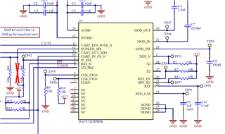
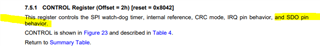
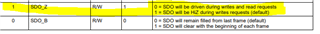
I have a design that has two of the DAC8742H HART modems connected to the same SPI bus. The issue that I am having is that the second IC is causing the amplitude of the SDO signals (MISO) from the first IC to be reduced to the point where the connected micro controller does not recognize the data. With my current setup we are only talking to one IC and I have verified that the CS line on the second IC is not being toggled (i.e. it remains high). When I probe the common SDO line (MISO) with my scope I can see the signals but they have a max voltage of just under 2V and when I cut the SDO trace to the second IC the voltage went up to just over 4V and I can communicate with the first IC. Do you have any idea why the second IC would be loading the line so much? I can see from the datasheet that when it is not in use it should be hi-Z.

Thanks,

Nathan

  • Nathan,

    Offhand, I'm not sure what the problem is. Do you have the IF_SEL pin connected to IOVDD or is is connected to some microcontroller? I wanted to check to see if the second device is accidentally in some UART mode. Do you have a schematic you can share?

    Joseph Wu

  • Hi Joseph,

    The first IC, the one I am able to get to work, is setup so that it can communicate over UART or SPI. The IF_SEL pin is connected to a GPIO on our uC. The second IC is pin strapped to SPI. Below is an expert of my schematic.

    Thanks,

    Nathan

  • Nathan,

    For the board, you had one device that you were able to get to work. For the second device, were you able to get that to work if you disconnected the second device? 

    If the MISO is only going to 2V, then it does sound like some sort of bus contention. For that, I was hoping to see a little bit more of the schematic. However, I would check to see more about the status of the second device. I would check to see if the IF_SEL pin is connected to ground. There does look like a test point there, but I would also measure the voltage at the pin directly (just in case). Second, I would also check to make sure that the /CS pin is high when you expect it to be. There does appear to be a pull-up, but it might be best to look at the pin for that as well.

    Just in case, can you show the scope photos of your communication as well? I don't know if it will reveal anything, but there might be something there.

    Joseph Wu

  • Hi Nathan,

    As per Joseph, it seem bus contention. could you check control register (0x2) values where you can set SDO output behavior.  Ensure not selected device SDO line will be Hi-z. set D[1] = 1 . Refer control register details at page 22. 

    Thanks ,

    Anbu Mani

  • HI Anbu,

    I had the setting for the control register reversed, so the output wasn't Hi-Z as I had thought. 

    Thank you for your help,

    Nathan

  • Hi Joseph,

    Thank you for your help. Anbu's comment below let me to find the issue with my code.

    Nathan