This thread has been locked.

If you have a related question, please click the "Ask a related question" button in the top right corner. The newly created question will be automatically linked to this question.

ADS1231: ADS1231 Interface

Part Number: ADS1231
Other Parts Discussed in Thread: ADS1232

Hey,

  We can't able to get a breakout board, So, We have built it by hand soldering on GPCB. We have followed the circuit reference which is referred to in the datasheet. Now, I have tried to interface ADS1231 and  Arduino. I can't able to read the output. Our, Actual target needs to interface ADS1231 with NRF53. So, help me out to resolve this 

Thanks & Regards

Navin

  • Hi Navin,

    Welcome to the E2E forum!  The ADS1231 is a pin configurable device (no internal registers) and must have all digital pins set to the appropriate logic levels and both analog and digital supplies must be at the nominal operating voltages.  You must also have a valid reference voltage connected to the ADC.

    Using an oscilloscope you can monitor the DRDY/DOUT pin and if the device is powered and operational you should see the output toggling at the selected data output rate (or SPEED pin setting).  If you do not see this happening than verify that the PDWN pin is set high and the power supplies are active at the ADS1231 input pins.

    If you see the DRDY/DOUT pin toggling appropriately, then you should verify the Arduino communication using the oscilloscope or logic analyzer (if available).  The analog input must be within a valid input range not exceeding the full-scale range input to the ADC.  The SCLK should dwell low, and capture data on the falling edge of SCLK.

    Can you send me your schematic, the configuration you are using, and the input voltage you have applied?  Also, can you send me scope shots of the communication and the results you are seeing?

    Thanks,

    Bob B

  • hi, bob, 

    I can't able to read the voltage also I think  some other fault which I have soldered,

    Instead of ADS1231, I have Got ads1232, With this, I have started my work. I have followed this example from Github(https://github.com/ciorceri/ADS1232). I can't able to read any data it shows only nan

  • Hi Navin,

    I can't help you with your code, but I can help you with the communication.  The first thing you need to do is to make sure the ADC is running.  Both the analog and digital supplies should be at the nominal operating voltage and the PDWN pin should be set high.  Make sure that there are no digital configuration pins floating, but instead are all set to a desired value.  With a logic analyzer or oscilloscope probe the the DRDY/DOUT pin and you should see it toggling at the rate set by the SPEED pin setting.

    Once this is verified you can start checking your code.  There is no CS on these devices, so you should make sure that SCLK is being driven by your code.  That usually requires that the some dummy data be placed in the transmit buffer.

    Send me scope shots of the communication, and from there we can troubleshoot further.

    Best regards,

    Bob B

  • hey bob

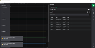
    I have followed what you have mentioned previously.  I can read some values through a logic analyzer. I have attached it here for your reference.

    Thanks & Regards

    Navin

  • Hi Navin,

    Unfortunately I cannot see the actual communication.  This appears to be a Saleae capture.  If so, would it be possible to export the file and attach to the thread so I can analyze the communication?

    The timing of the various data reads appear to be sporadic.  Also, there should be groupings of 3 bytes for every conversion result.  So it is not clear what else may be wrong with the communication. 

    As I said previously, it would be helpful to know if the ADC device is operating correctly.  The plot should show that DRDY/DOUT is toggling every 100ms (SPEED set low) or every 12.5ms (SPEED set high).  Can you monitor and verify you see this?

    Best regards,

    Bob B

  • Hi bob,

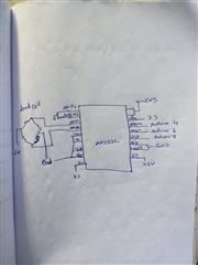
    The below image is my circuit connection, KIndly correct it.  If it is wrong. Now, I can't able to read any data via Logic analyzer

    Thanks & Regards

    Navin.

  • Hi Navin,

    The ADS1232 has 24 pins, and none of the pins in your diagram are labeled.  You must have a valid reference voltage connected.  There is no indication showing the gain pins and the settings used.  Also there does not appear to be a 100nF cap placed between the cap pins.

    You originally tried using the ADS1231.  The ADS1232 is not pin compatible with the ADS1231.

    It is not clear how you are prototyping your solution.  Are you using a breakout board?  Can you send me a picture of your setup?

    Best regards,

    Bob B

  • HI BOB,

    Now, We can read the Values from the DT of ADS123. Now, I need to know how to convert ADC value to weight. Give me some samples to achieve 

    Thanks & Regards

    Navin

  • Hi Navin,

    The conversion from voltage to weight is dependent on the sensitivity of the load cell.  Load cell sensitivity is given by the manufacturer as mV/V which refers to the output of the load cell per voltage of excitation to achieve the full scale output rating of the load cell.  

    As an example, let's say the sensitivity of the load cell is 2mV/V for a full-scale of 10kg.  This means the load cell is going to output 2mV if the excitation is 1V and 10kg is applied to the load cell.

    If the excitation voltage is 3.3V, then the maximum load cell output will be 6.6mV for this example.  The full-scale range (FSR) of ADS123x devices is +/- 0.5 * Vref/Gain.  If Vref is the same as excitation and the gain is 128, then the FSR = 2*(0.5)*3.3/128, or 25.78mV (+/- 12.89mV).  The value of one code (LSB) is FSR/(2^24-1) = 25.78mV/16777215 = 1.537nV.

    To determine the value of grams per code you consider the proportion of load cell output voltage divided by the LSB value as being equal to the load cell full-scale weight divided by a single code.  So rearranging you get full-scale output in grams * LSB / full-scale voltage output.  10kg * 1.537nV / 6.6mV = 2.33mg per code.

    The final result is to take the ADC return value and multiply times the grams/code result.

    Best regards,

    Bob B