This thread has been locked.

If you have a related question, please click the "Ask a related question" button in the top right corner. The newly created question will be automatically linked to this question.

ADS8684: Query regarding differential signal measuring using ADC

Part Number: ADS8684
Other Parts Discussed in Thread: INA828

Hi.

Usually we do ADC design with an instrumentation amplifier at the input to read the sensor signals. In the case of ADS8684 it is showing that it has already amplifier section inside the ADC it self. So should I use an external instrumentation amplifier or not?

If yes, How to implement this without adding a negative voltage rail. I found that there is no requirement for negative voltage rail for ADS8684 as it supports voltage range from -10V to +10V. It requires only a 5V supply. 

  • Hi Jishnu,

    ADS8684 only supports single-ended(SE) signals, either bipolar (+/-10.24V or +/-5.12V, +/-2.56V) or unipolar (0-10.24V or 0-5.12V). You still external instrumentation amplifiers or other circuits for differential to single-ended signal conversion. 

    The internal PGA is implementing the signal conditioning from SE HV bipolar to proper signal range for internal ADC core.

    I hope this helps.

    Best regards,

    Dale

  • Hi Dale,

    Thank you for your response & Sorry for misleading by the term "differential". In my case what I want to measure is a Bipolar signal which ranges between -10V and +10V.

    So I think I need not convert the signal to SE. Should I use and external Instrumentation amplifier to Improve the signals or should I feed the input directly to the ADC inputs. The usage of an external instrumentation amplifier without -ve supply will remove the -ve range of the signal, won't it? so how should I use this? 

    Thank you

  • Hi Jishnu,

    Can you confirm your +/-10V signal is a single-ended signal and not a differential +/-10V signal? If it's a single-ended signal, you do not need external instrumentation amplifier or other amplifier. Instrumentation amplifier can be easily used to convert a differential signal with a common-mode voltage to a single-ended output with low offset, low noise, easy and high gain setting.

    Best regards,

    Dale

  • Hi Dale,

    I will verify my signal is really single ended or not.

    In case of differential, If I am using an Instrumentation amplifier without negative power supply, I wont get the feature to measure negative ranges of signal right? So can you suggest a way to implement this without need of negative supply?

  • Hi Jishnu,

    Update: let me explain it a little bit. Below are examples based on INA828 instrumentation amplifier:

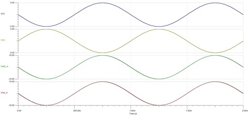
    1. When +/-15V power supplies are applied to the INA828 and the input signal is a differential +/-10V (Vina_in), the output of INA828 is +/-10V when the Gain is 1. The full dynamic range (-10V~10V) of ADS8684 is utilized. Both your positive and negative signals can be measured. See the timing from the TI-TINA simulation below.

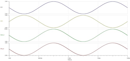
    2. When only +15V power supply is applied to the INA828, your input signal should be limited to a differential +/-5V (Vina_in) because of +15V supply. The output of INA828 is 0~10V when the Gain is 1 and the bias voltage(Vref) is 5V.  See the timing from the TI-TINA simulation below.  The full dynamic range (-10V~10V) of ADS8684 is only utilized for half (0~10V). Both your positive and negative signals can still be measured, however your actual resolution of ADC is only 15-bit. If you want to support -10V~10V differential signal, the single power supply of INA828 should be higher than 20V. 

    I attached these two simulation files, you can modify them and do some experiments in TI-TINA.

    To utilize the full dynamic range of ADS8684 to measure your differential -10V~10V signal, dual power supplies for INA828 are required. TI has some power devices which can be used to simply generate a negative power supply, you can check or ask on E2E forum for power devices.

    If your signal is single-ended +/-10V, you can simply connect it to the ADS8684 for measurement.

    Best regards,

    Dale

    /cfs-file/__key/communityserver-discussions-components-files/73/INA828_5F00_Dual-Power-Supply_5F00_TINA_2D00_TI.TSC

    /cfs-file/__key/communityserver-discussions-components-files/73/INA828_5F00_Single-Power-Supply_5F00_TINA_2D00_TI.TSC

  • Hi Dale,

    Thank you for the clarification. Today I confirmed my signal is Single ended Bipolar, so I will use the design without INA.

    I have one more doubt.

    In my case the frequency may become greater than 15 KHz, In datasheet I found there is an internal LPF which has a cutoff of 15KHz. Can I Adjust the frequency of the Internal LPF. Or how can I use the device to measure such signals

    Thanks & Regards

    Jishnu

  • Hi Jishnu,

    No, you can not change the BW of internal LPF. Also, when you use this ADC to measure a high frequency signal (e.g. 15kHz), your signal will be attenuated and distorted by the LPF. There are two possible solutions:

    1. Use an ADC with integrated AFE and high impedance like ADS8684 but has a higher BW of LPF. ADS8686S has a 376kHz BW of internal LPF, however it has 16 input channels.

    2. Use a conventional ADC without LPF, however an high BW amplifier is required to drive the ADC on each channel. Please see some ADCs in the following link. For example, AD7067: 16-bit, 8-ch, 800ksps with multiplexer.

    /cfs-file/__key/communityserver-discussions-components-files/73/ADC_5F00_16_2D00_bit_5F00_8_2600_4_2D00_ch-without-AFE-and-LPF.xlsx

    Best regards,

    Dale