Other Parts Discussed in Thread: ADS8681
Hello guys,
One of my customers is evaluating ADS8699 on their own board for their new products.
In the evaluation, they found that the device RVS pin level doesn't go high from low after /RST transition from L to H.
The device datasheet (Document #: SBAS777B) says the following in 7.4.2.1 RESET state on page 39.
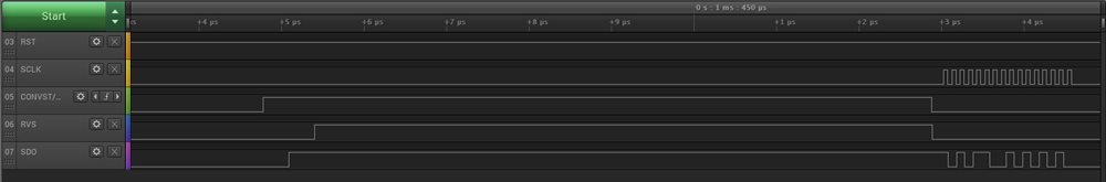
"In order to exit any of the RESET states, the RST pin must be pulled high with CONVST/CS and SCLK held low.
After a delay of tD_RST_POR or tD_RST_APP, the device enters ACQ state and the RVS pin goes high."
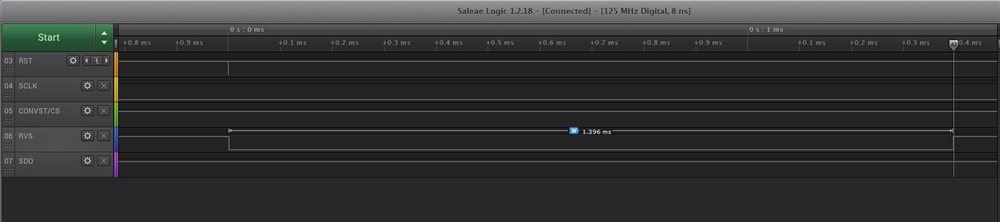
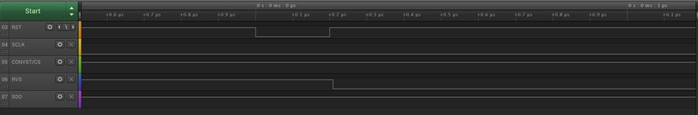
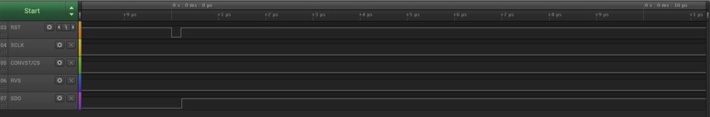
The customer sent 1us low /RST pulse (tr/tf=3ns) to ADS8699 with CONVST/CS and SCLK held low after powered up .
But after that, RVS didn't go high from low (low level was kept).
Do you know why the RVS signal didn't go high?
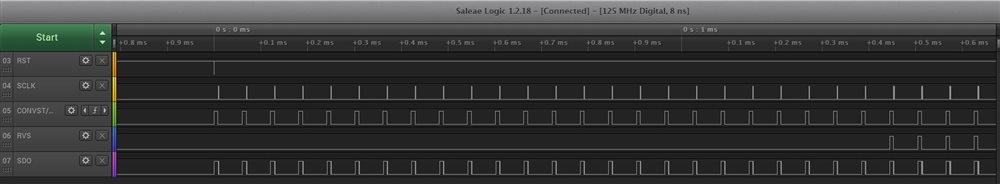
Also the customer sent the low /RST pulse to ADS8699 after powered up with CONVST/CS held high. Then the RVS went high.
Could you please give me the cause of the phenomenon if you know it?
Best regards,
Kazuya.